


20 Advanced Functions
Note
A point to notice
Info.
Supplementary information
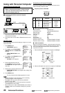
Using with Personal Computer
Configuring the time lapse VCR
Important notice:
• Before connecting the hardware, unplug the power
cord of the VCR from the wall outlet, and turn the
personal computer power off.
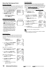
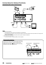
Connecting the VCR to a personal computer
1. Connect the RS-232C cross cable to the RS-232C terminal
of the personal computer.
2. Connect the other end of cable to RS-232C terminal on the
VCR.
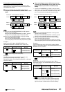
RS-232C setting
Set the RS-232C interface board setting by using the on screen
menu of the VCR.
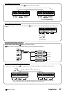
1. Press MENU button.
• <MAIN MENU> appears.
2. Turn JOG to select CLOCK/FIRST
TIME SET UP and turn SHUTTLE to
the right.
• <FIRST TIME SET UP> menu
appears.
3. Turn JOG to select RS-232C and turn
SHUTTLE to the right.
• <RS-232C> menu appears.
4. Change the parameter value by
turning JOG to the left or right and
turn SHUTTLE to the right to store the
new value.
5 Repeat step 4 until all of the items are set.
• <FIRST TIME SET UP> menu appears after setting VCR
ADDRESS.
6. Press MENU button.
• The day and present time display appears on screen.
Note
• Set all parameters to the same values as the controlling
personal computer or other equipment.
• The PARITY BIT cannot be used when the DATA BIT
LENGTH is set to 8BIT.
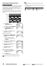
• When controlling only one VCR via the personal computer,
VCR ADDRESS is set to NONE.
• When VCRs have a unique VCR ADDRESS (from VCR01 to
VCR255), VCRs can be controlled remotely via a personal
computer.
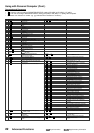
Connecting to a Personal Computer
A personal computer that has an RS-232C serial port can be
used to remotely control the VCR.
Physical protocol of RS-232C
Data communication settings
Synchronization Asynchronous
Transmission rate 1200/2400/4800/9600 bps
Data bit length 8bit/7bit
Stop bit length 1bit/2bit
Parity bit Nil/Even/Odd
Xcontrol Nil
S parameter Nil
CS-RS hand-shake With
Delimiter code for send CR(0DH)/CR(0DH)+LF(0AH)
Delimiter code for receive CR(0DH)/CR(0DH)+LF(0AH)
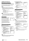
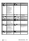
Cable connections
Before connecting the hardware, unplug the power cord of the
VCR from the outlet, and turn the personal computer power off.
Connect the RS-232C terminal of the VCR to the personal
computer’s serial port.
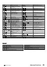
1. When the RS-232C connector of the computer is D-SUB 25pin.
2. When the RS-232C connector of the computer is D-SUB 9pin.
AUDIO VIDEO
OUT OUTIN
REMOTE MIC
IN
RESET
ALM RST
IN
RECGND ALM
MODE
CLK
OUT
CALL
BATTERY
OPEN
Personal computer
RS-232C
terminal
RS-232C cross cable
RS-232C
terminal
<MAIN MENU>
DISPLAY
TIMER PROGRAM
RECORDING SET UP
REAR TERMINAL
<FIRST TIME SET UP>
TIME DATE ADJUST
TAPE END STOP
QUASI V-SYNC ON
VIDEO MODE AUTO
TAPE LENGTH T-120
BUZZER WRNG
RS-232C
<RS-232C>
TRANSMISSION RATE 1200
DATA BIT LENGTH 8BIT
STOP BIT LENGTH 1BIT
PARITY BIT NONE
DELIMITER<SEND> CR•LF
DELIMITER RECEIVE CR
<RS-232C>
TRANSMISSION RATE 1200
DATA BIT LENGTH 8BIT
STOP BIT LENGTH 1BIT
PARITY BIT NONE
DELIMITER<SEND> CR•LF
DELIMITER<RECEIVE> CR
VCR ADDRESS NONE
RS-232C
D-SUB 9pin male
5 4 3 2 1
9 8 7 6
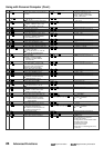
No.
2
3
4
5
6
7
8
Signal line
names
Meanings
Receive data
Transmit data
Data terminal ready
Signal ground
Data set ready
Request send
Clear to send
Directions
(from VCR side)
INPUT
OUTPUT
OUTPUT
–
INPUT
OUTPUT
INPUT
RD
SD
ER
SG
DR
RS
CS
FRAME
RD 2
SD 3
ER 4
SG 5
DR 6
RS 7
CS 8
1 FG
2 SD
3 RD
4 RS
5 CS
6 DR
7 SG
20 ER
D-SUB 9 pin female
(VCR)
D-SUB 25 pin male
(Computer)
RD 2
SD 3
ER 4
SG 5
DR 6
RS 7
CS 8
2 RD
3 SD
4 ER
5 SG
6 DR
7 RS
8 CS
D-SUB 9 pin female D-SUB 9 pin female
FRAMEFRAME