


36 Others
Note
A point to notice
Info.
Supplementary information
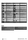
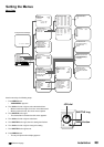
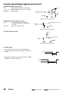
Control Input/Output Signals and Circuit
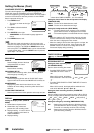
16 ms
+12 V
0 V
8 ms
+12 V
0 V
CLK OUT signal
• When F is selected in CLOCK OUT of REAR TERMINAL
menu (at 6H or 8H mode) or while recording in L18H-128H or
0H mode.
• When REC-1 to REC-60 is selected in CLOCK OUT of REAR
TERMINAL menu (at 6H or 8H mode).
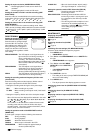
CLK OUT terminals (screw)
DC 12 V
10 kΩ
GND
CLK OUT
100 Ω
<Interface circuit inside the VCR>
ALM/MODE/CALL OUT terminals (screw)
Active : “L” level voltage (0 to + 0.4 V) output;
max. drive current 50 mA (+5 V DC)/10 mA
(+24 V DC)
Non active : Open; max. voltage +24 V DC
GND
ALM/MODE/CALL OUT
<Interface circuit inside the VCR>
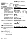
ALM/RST/REC IN terminals (screw)
Active : When input terminals are short-circuited to
GND or “L” level voltage (0 to +1.6 V) applied.
Time for active : 0.1 sec. or over.
Non active : Open the input.
DC 5 V
10 kΩ
22 kΩ
22 kΩ
0.047 µF
GND
ALM/RST/REC IN
<Interface circuit inside the VCR>