


Remote Control Panel User’s Guide ● Rev 00 11
Connectivity Diagram
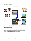
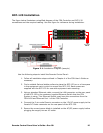
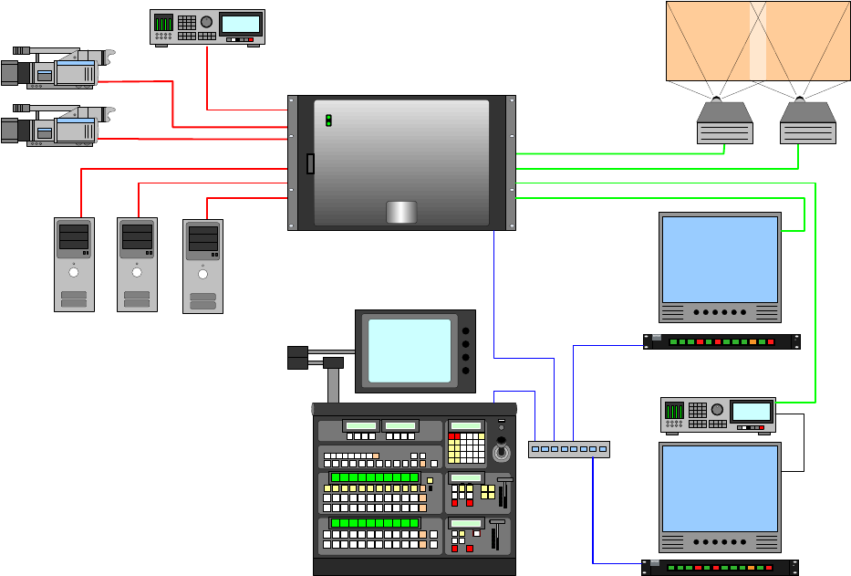
The figure below illustrates a basic FSN Series system, showing a typical usage of the
Remote Control Panel to switch inputs for FSN AUX outputs.
N1-1
-- -- - --
N2-1
N1-2
-- -- - --
N2-2
N1-3
-- -- - --
N2-3
N1-4
-- -- - --
N2-4
N1-5
-- -- - --
N2-5
N1-6
-- -- - --
SB-1
N1-7
-- -- - --
SB-2
N1-8
-- -- - --
SB-3
U1-1
-- -- - --
75CB
U1-2
-- -- - --
SMPTE
SHIFT
AUTO
TRANS
RMT-120
N1-1
-- -- - --
N2-1
N1-2
-- -- - --
N2-2
N1-3
-- -- - --
N2-3
N1-4
-- -- - --
N2-4
N1-5
-- -- - --
N2-5
N1-6
-- -- - --
SB-1
N1-7
-- -- - --
SB-2
N1-8
-- -- - --
SB-3
U1-1
-- -- - --
75CB
U1-2
-- -- - --
SMPTE
SHIFT
AUTO
TRANS
RMT-120
EIC Monitor
Record
Station
AUX Output
Ethernet
Remote Control Panel
Remote Control Panel
AUX Output
Figure 1-1: FSN System Connectivity Diagram
Application Questions
At Barco, we take pride in offering unique solutions to demanding technical problems. If
you have application questions, require further information or would like to discuss your
application requirements in more detail, please call (866) 469-8036. Our Customer
Support Engineers will be happy to supply you with the support you need. Refer to
Appendix C, “Contact Information” at the end of this manual.