8-10
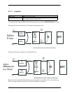
8.3.1.1 Definition of Line Status LEDs for T1 Span 1 and T1 Span 2 (first two
LEDs)
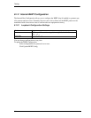
8.3.1.2 Definition of Test LEDs for T1 Span 1 and 2 (third and fourth LEDs)
8.3.1.3 Definition of V.35 Status LED (last LED)
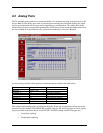
8.4 DIP Switches
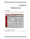
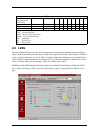
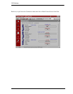
This screen shows the settings of the DIP switches on the connected Access Bank II and the cards
that populate the Access Bank II unit, after a read operation. You must be connected. Click on the
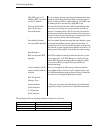
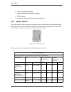
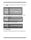
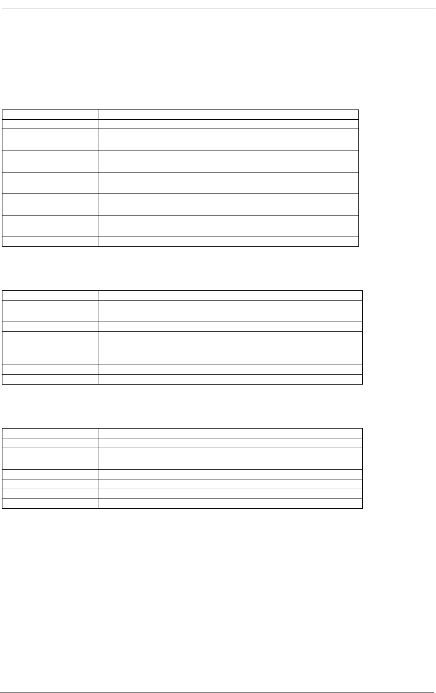
State Meaning
Off Loss of T1 signal, no pulses received.
Green Access Bank II is in frame with a frame-bit error rate less than
10e-5.
Flashing Green Access Bank II is in frame, but frame-bit error rate exceeds 10e-
5.
Red AIS (Unframed All Ones Signal) received from the incoming
T1 span.
Flashing Red Access Bank is not synchronized to the incoming T1 line, but
no AIS is being received.
Yellow BPV errors received on the T1 line that are not due to B8ZS line
coding.
Flashing Yellow Yellow Alarm received from the T1 line.
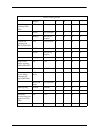
State Meaning
Green Normal operations. Trunk processing, self test, and network
loopback inactive.
Flashing Green T1 Self Test local loopback passed.
Red T1 Self Test local loopback failed due to one or more of the
following conditions: T1 Loss of Signal, Out of Frame, Improper
Line Code Received, ESF or BPV errors received.
Yellow Channels held in Trunk Processing for this T1 span.
Flashing Yellow Network loopback active for this T1 span.
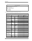
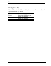
State Meaning
Off No T1 channels assigned to V.35 port.
Green CD (RLSD) and RTS leads active. T1 channels assigned and
operative.
Flashing Green V.35 in loopback to DTE equipment.
Red CD (RLSD) lead is inactive because assigned T1 is inoperative.
Yellow CD (RLSD) lead active. RTS lead inactive.
Flashing Yellow V.35 in loopback to T1 line.


