


Getting Started
Here’s a brief overview of the steps needed to integrate the IP-HDVR.
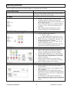
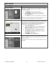
Front Panel Setup
Use Front Panel Setup to select output, format, RS-232
parameters, and/or Ethernet settings.
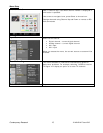
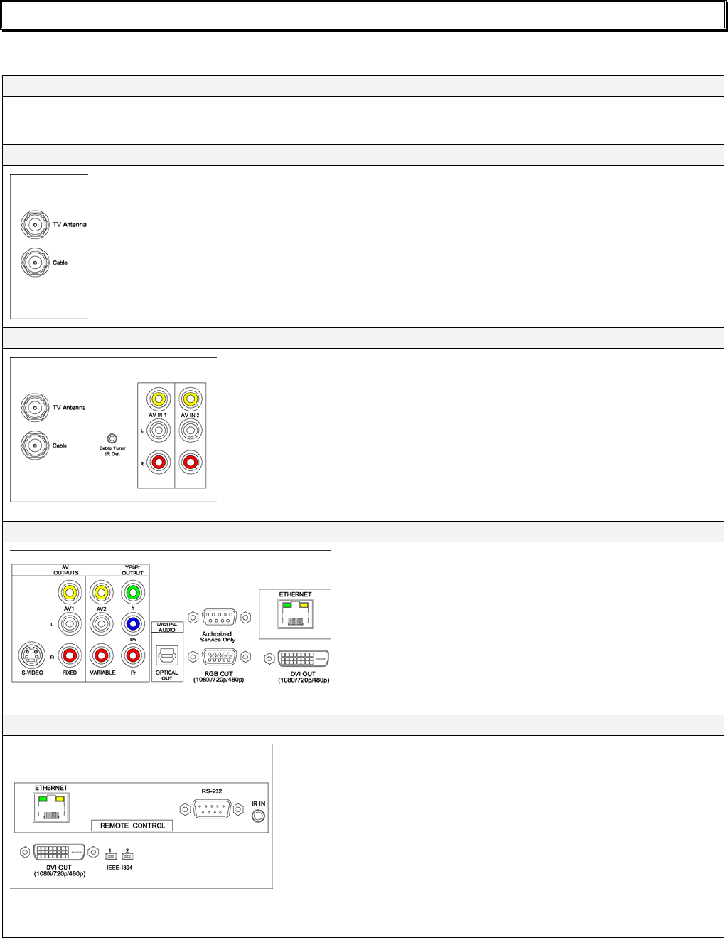
RF Input
• Connect TV Antenna and/or Cable RF feeds.
• TV Guide Setup will determine if tuner will
search for off-air only or cable analog/digital and
off-air digital channels.
• After TV Guide Setup (p10), use Channel Menus
to search, screen, and test broadcast channel
operation.
• Use TV Guide Channel Setup (p19) to filter
channels displayed in the Program Guide.
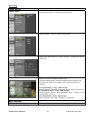
Cable Box/AV Input Integration
• Connect Cable Box AV output to:
o AV IN 1 inputs
o Cable input for AV on channel 2, 3, or 4
• Connect G-Link IR cable to Cable Tuner IR Out
• Attach IR emitter to underside of cable box, IR
emitter below the box’s IR sensor
• TV Guide Setup will link tuner to input and IR
codes for cable box control
• If you are not connecting a cable box, both AV
inputs can be switched through the tuner
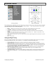
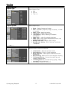
AV Outputs
• Connect high-definition display to Component,
RGB, or DVI outputs (Use optional adapter to
connect an HDMI source to the DVI output)
• Connect video display to AV 1 or AV 2 outputs
• The IP-HDVR can switch between HD and video
outputs (no video is present when an HD video
output is selected)
• Connect audio equipment to Optical and/or
analog outputs – AV 1 is fixed, AV 2 is variable
• Audio is always present for all outputs
Control
• Connect Ethernet or RS-232 control cable to
control system
• Use front-panel menus to set IP address or RS-
232 parameters
• The IP-HDVR can also provide pass-through
bidirectional control of a display through the RS-
232 control port when the tuner is integrated via
the Ethernet port
• For IR control, connect external IR sensor or
wired IR system control port to IR IN, discrete IR
codes are available in AMX, Crestron, and Pronto
format
Contemporary Research 10 IP-HDVR HD Tuner-DVR