


18
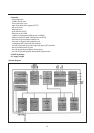
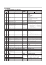
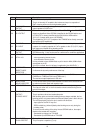
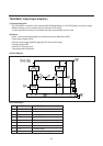
No Name Description
to the luminance input pin 27.
The pin is internally AC coupled to the luminance clamp via a capacitor of
50pF; clamping action occurs during burstkey period.
28 LUMINANCE The luminance output signal is approximately l V black-white with typical
OUTPUT output impedance of 25O ohm.
29 B-Y OUTPUT The maximum output impedance of pins 29 and 30 is 500 when PAL/NTSC
30 R-Y OUTPUT signals are identified. When SECAM is identified by the SECAM add-on and
no PAL/NTSC is already identified by the ASM, then the ASM sets the
-(B-Y)/-(R-Y) output switch open (via DEMSW).
This enables the -(B-Y)/-(R-Y) outputs of the TDA8395 to be directly connected
to pins 29 and 3O respectively.
31 B-Y INPUT The -(B-Y),-(R-Y) output signals (supplied from baseband delay line) are AC
32 R-Y INPUT coupled, via a coupling capacitor of 10nF or greater, to the -(B-Y)/-(R-Y) inputs;
both inputs are clamped during burstkey period.
33 SECAM REF The SECAM reference output is directly connected to pin l of the TDA8395 for
OUTPUT SECAM decoding ; it also can be used as a reference for comb filter applications.
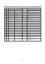
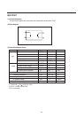
34 X-TAL 3.58 To ensure correct operation of both:
35 X-TAL 4.43 - colour processing internal circuits,
- sync calibration internal circuits,
it is only allowed to have 3.6MHz Xtals on pin34: both 4.4MHz,3.6MHz Xtals
are allowed on pin 35.
If pin 35 is not used: then it is left open in application (also XA,XB=O,1 ).
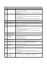
36 LOOP FILTER One of the important aspects of the PLL is the 1oop filter connected to pin 36;
BURST PHASE it influences the dynamic performance of the loop.
DETECTOR
38 CVBS OUTPUT The output amplitude is 1Vpp (transfer gain ratio between CVBS1int or
CVBS2ext or CVBS3ext/Ys-vhs and CVBSout is 1).
The maximum output impedance is 250 ohm.
39 BLACK PEAK For the correct working of the black stretcher an external time constant should
HOLD CAPACITOR be added at the black peak hold capacitor input.
40 HOR OUTPUT This open collector output is meant to drive the horizontal output stage.
The output is active low, i.e. the line transistor should conduct during the low
period of the output.
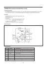
41 SANDCASTLE Pin 41 is a combined input/output pin.
OUTPUT/ The pin provides a three level sandcastle pulse.
FLYBACK INPUT Both burstkey pulse and vertical blanking pulse are always available, the line
blanking pulse is only present when the external flyback pulse is fed to this pin.
The line flyback pulse, fed to this pin is used for two functions:
- input signal for the PHI-2 1oop and
- RGB line blanking. (without flyback pulse blanking occurs only during the
burstkey pulse)
To ensure correct working of the delay line and SECAM add-on, the output
should not be loaded with more than:
- Sandcastle input delay line TDA 4665
- Sandcastle input SECAM add-on TDA 8395
42 PHI-2 FILTER / The loopfilter is a first order filter.
FLASH PROTECT This pin requires a capacitor (C) only.