


19
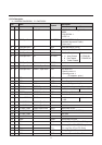
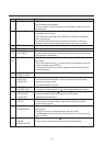
No Name Description
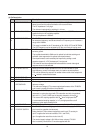
A flash protection becomes active when this pin is forced >6V. The horizontal
drive is switched-off immediately.
Once the voltage is <6V the horizontal drive is switched-on again via the slow
start procedure.
43 PHI-1 FILTER The loopfilter connected to pin 43 is suitable for various signal conditions as
strong/weak and VCR signal.
This is achieved by switching of the loopfilter time constant by changing the
PHI-1 output current.
Via I2C bus FOA/B, different time constants can be chosen, including an
automatic mode which gives optimal performance under varying conditions.
44 GROUND To this pin are connected the IC-substrate and horizontal output.
45 EAST-WEST DRIVE not used
46 VERT DRIVE + The vertical drive has a current output. The output is balanced which ensures
47 VERT DRIVE - a good common mode behavior with temperature and makes the output signal
less sensitive for disturbances.
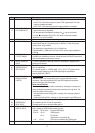
48 IF INPUT The PLL frequency range is 32-60MHz with corresponding VCO frequency
49 64-120MHz.
The IF input impedances is 2 in parallel with 3pF and matches the required
load for commonly used SAW filters.
A DC coupling is allowed, so no series capacitors between SAW filter and IF
input are necessary.
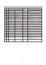
50 EHT/OVERVOLTAGE not used
PROTECT INPUT
51 VERT This pin requires a capacitor to ground of l00nF +, - 5%.
SAWTOOTH The optimal sawtooth amplitude is 3.5V and is determined by the external
CAPACITOR capacitor and charge current.
The sawtooth bottom-level is 2V.
52 REFERENCE This pin requires a resistor to ground.
CURRENT INPUT The optimal reference current is 100 . which is determined by this resistor.
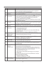
53 AGC The AGC capacitor value is 2.2 and has been defined for an optimal
DECOUPLING compromise between AGC speed and tilt for all AGC modes
CAPACITOR (negative/positive modulation).
54 TUNER AGC This output is used to control (reduce) the tuner gain for strong RF signals.
OUTPUT The tuner AGC is an open collector output which is acting as a variable
current source to ground.
55 AUDIO Only a capacitor has to be connected to this pin that defines the deemphasis
DEEMPHASSIS time constant.
The signal is internally connected through to the Audio switch.
The deemphasis output is fixed, thus not controlled by the volume, and can be
used for SCART.
56 DECOUPLING This pin requires a capacitor of 10 connected to ground.
SOUND The pin acts as a low pass filter needed for the DC feedback loop.
DEMODULATOR