


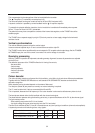

36
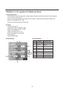
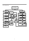
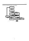
Video amplifiers
Three TDA6106Q integrated video amplifiers drive cathode of the picture tube directly.
They are protected against CRT flashover discharges and ESD (electro static discharge).
The three video amplifiers, have a beam current output I black, used by the TDA8374 black current loop to control
the black level on the cathodes.
The outputs can be connected together because the black current 1oop sequentially controls the black level for each
cathode.
The amplification of the TDA6106Q is set by the resistors between pin 3 and 9 and between pin 3 (negative-input) and
the TDA8374 output.
There are no alignment any more on the CPT panel, because of the automatic black current stabilization and because
the white point adjustment can be done in the TDA8374 via I2C bus.
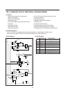
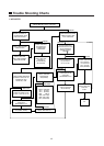
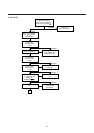
Power Supply STR-S5707
(1) VIN terminal, start-up circuit
A start-up circuit is to start and stop a operation of a control IC by detecting a voltage appearing at a VIN terminal
(pin-9).
At start up of a power supply, when a voltage at the VIN terminal reaches to 8V (typical) by charging up C807 by
the function of a start-up resistor, R803, a control circuit starts operating by the function of the start-up circuit.
After the control circuit starts its operation, power source is obtained by smoothing voltage appearing at winding of
pin6-7 of T801.
(2) Oscillator, F/B terminal voltage (Pin 7)
A oscillator generates pulse signals which turns a power transistor on and off by making use of charge and discharge
of C1 and C2 incorporated in the Hybrid IC.
Constant voltage control of a switch-mode power supply is performed by changing both ON-time and OFF-time except
when the load is light (ex. remote control stand-by mode of TVs).
The ON-time is controlled by changing a current charged by C1, which is as the result of that the detection winding of
pin5-7 of T801, which detects a change of voltage in a secondary side, connected to the sensing terminal (Pin 7) has the
current in accordance with an output signal from an output voltage detection circuit (an error amplifier) built in.
As an AC input voltage to the power supply gets the higher and a load current the smaller, the current flowing to the
SENS terminal gets the larger, and the ON-time gets the shorter.
(3) Function of INH terminal (Pin 6), control of OFF-time
Signal to the INH terminal is used as inputs to COMP.1 and COMP.2 inside of the control IC.
A threshold voltage of COMP.1, VTH1 is set at 0.75V (Ta=25°) and an input signal to a drive circuit becomes almost
0V (the power transistor is in OFF mode) when a voltage at the INH terminal reaches the VTH1.
A threshold voltage of COMP.2, VTH2, is set at 1.5V (Ta=25°).
When the INH terminal voltage reaches VTH2, an output from COMP.2 reverses (the power transistor is in on mode).
Quasi-resonant operation
By inputting the voltage of winding of pin6-7 of T801 which is synchronized with the energy discharge time of a
secondary winding, pin14(or 15)-16 of T801, to the INH terminal through D805 and R809, quasi-resonant operation
can be achieved.
When the power transistor turns off and a voltage higher than VTH2 is applied to the INH terminal, C3 immediately
discharges and then starts charging again.
Even after the discharge of energy of a secondary winding is completed, VINH does not immediately increases.
When it gets lower than VTH1, the transistor turns on.