


35
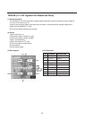
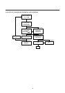
TDA8356 vertical deflection.
The TDA8356 is a vertical deflection circuit.
It can be used in 90 deflection systems with frame frequencies from 50 up to 120 Hz
With its bridge configuration the deflection output can be DC coupled with few external components.
Only a supply voltage for the scan and a second supply for the flyback are needed.
The TDA8356 can drive max.2A.
The vertical drive currents of TDA8374 pins 47 and 46 are connected to input pins l and 2 of the TDA8356.
The currents are converted into a voltage by a resistor between pins 1 and 2.
Pin2 is on a fixed DC level (internal bias voltage) and on pin l the drive voltage can be measured (typical 1.8 Vpp).
The drive voltage is amplified by ‘A’ and fed to two amplifiers ‘B’ and ‘C’, one is inverting and the other is a non
inverting amplifier.
The outputs (pins 4 and 7) are connected to the series connection of the vertical deflection coil and feedback resistor .
The voltage across feed back resistor is fed via pin 9 to correction amplifier ‘D’, to obtain a deflection current which is
proportional to the drive voltage.
The supply voltage for the TDA8356 is 16V at pin 3.
The flyback generator has a separate supply voltage of 45V on pin 6.
The guard pulse is useful to synchronize OSD.
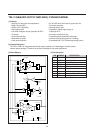
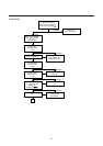
Horizontal deflection
The circuit contains horizontal drive, line output transformer.
The horizontal driver pulses from the TDA8374 are amplified in the horizontal drive circuit, to get sufficient base-drive
current for the high voltage switching transistor Q401.
During the horizontal scan period( =52 s) Q401 will conduct, and a sawtooth current flows from +110/123V through the
primary winding of the FBT to ground.
After this time Q401 is switched off and the energy stored in the FBT during the scan period will be transformed to the
flyback capacitor C410.
This energy transfer will take place in a cosine shape because the primary of the FBT and C410 from a resonant circuit.
The time the energy is transferred from FBT to C410 and back to the FBT, is called the flyback time and will take place
in about 12 s.
The flyback peak voltage is about 8 times the scan voltage.
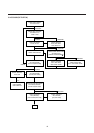
In series with the horizontal deflection coil there is a (damped) linearity corrector coi1.
During the scan there is some loss in the resistance of the deflection coi1.
In the first part of a line the linearity corrector stores some energy in a permanent magnet until it is saturated.
This improves the linearity of the horizontal scan speed.
The required S correction for the picture tube can be adjusted with the value of C411.
The beam current limiting information (BeamCurr) is derived from the foot of the H.V winding of the FBT.
This is connected via resistor to +8V.
As the beam current increase, the voltage on line BeamCurr decreases.
BeamCurr is damped by a integration filter before it is fed back to TDA8374 pin 22.
The TDA8374 will decrease the contrast (and eventually the brightness) to limit the average beam current.