


34
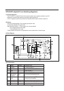
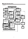
TDA8395 SECAM decoder
The TDA8395 is an alignment-free SECAM colour decoder, including a Cloche filter, demodulator and line
identification circuit.
The Cloche filter is a gyrator-capacitor type.
Its frequency is calibrated in the vertical retrace period.
The calibration reference( pin 1 ) is obtained from the TDA8374 color X-tal oscillator (pin 33).
Pin 7 is a decoupling for the Cloche reference.
The voltage change at this pin due to leakage currents should be lower than 10 mV, during field scan, resulting in a
capacitor of minimal 100 nF.
Pin 8 is the reference capacitor for the PLL.
The voltage variation during field scan at this pin should be lower than 2 mV , resulting in a capacitor of 220 nF.
The sandcastle input (pin 15) is connected to TDA8374 pin 41 and is used for generation of the blanking periods and
provides clock information for the identification circuit.
The CVBS source select output (TDA8374 pin 38) supplies SECAM chroma to pin 16 of the TDA8395.
This is demodulated by a PLL demodulator, that uses the reference frequency at pin l and a bandgap reference to
obtain the desired demodulation characteristic.
If the digital line identification in theTDA8395 detects SECAM, pin 1 will sink a current of 150 (A out of TDA8374
SECAMref pin 33.
When the TDA8374 has not detected PAL or NTSC, it will respond by increasing the voltage at pin 33 from 1.5V to 5V.
Now the TDA8374 color difference outputs pin 30 and 29 are made high-ohmic and the TDA8395 output pin 9 and 10
are switched on.
These outputs will be disconnected and high-ohmic when no SECAM is detected for two frame periods, the decoder
will be initialized before trying again.
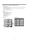
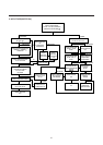
Base band delay line TDA4665
TDA4665 is an integrated double baseband delay line of 64 S.
It couples to the TDA8374 and TDA8395 without any switches or alignments.
The TDA4665 consist of two main blocks:
- Two delay lines of 64 sec in switched capacitor technique
- Internal clock generation of 3 MHz, line locked to the sandcastle pulse
The TDA4665 operates according to the mode demanded by the colour transmission standard:
- For PAL it operates as geometric adder to satisfy the PAL demodulation requirements
- In NTSC mode it reduces cross-colour interference (comb-filtering)
- For SECAM it repeats the colour difference signal on consecutive horizontal scan lines.
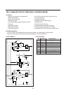
A sandcastle pulse is connected to pin 5.
The top pulse voltage (should not exceed 5 V) can be directly coupled to the 5 V sandcastle output of the TDA8374.
The R-Y and B-Y colour difference signals (from TDA8374 pins 30 and 29) are AC-coupled and clamped by the
input stages at pins 16 and 14.
An internal 6 MHz Current controlled oscillator is line locked via a PLL to the sandcastle pulse at pin 5.
This clock drives the delay lines to obtain the required 64 sec.
Sample and hold low pass filters supress the clock signal.
The original and the delayed signals are added, buffered and fed to the output pins 11 and 12.
These are AC-coupled to the R-Y and B-Y colour difference input pin 32 and 31 of TDA8374.
The TDA4665 needs a 5 V supply voltage on pin l for the digital part and on pin 9 for the analog part.