


33
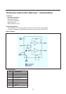
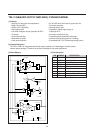
Integrated video filters
The TDA8374 has alignment-free internal luminance delay, chroma bandpass and chroma trap.
They are implemented as gyrator circuits tuned by tracking to the frequency of the chroma Xtal oscillator.
The chroma trap in the Y signal path is by-passed when Y/C input is selected (S-VHS ).
For SECAM an extra luminance delay is build-in, for correct delay of the luminance signal.
RGB output and black current stabilization
The colour difference signals (R-Y, B-Y) are matrixed with the luminance signal (Y) to obtain the RGBout output
signals (pins 21,20,29).
In the TDA8374 the matrix type automatically adapts to the decoded standard (NTSC,PAL) .
Linear amplifiers are used to interface external RGBrn signals (pins 24,25,26) from the SCART connector.
These signals overrule the internal RGB signals when the data insertion pin 26 (FBI) is switched to a level between
1.0V and 3.0V.
The contrast and brightness control and the peak white limiter operate on both internal and external RGB signals
R,G and B each have their own, independent gain control to compensate for the difference in phosphor efficiencies
of the picture tube: so called “white point” adjustment.
The nominal amplitude is about 2V black to white, at nominal input signals and control settings.
TDA8374 has a black current stabilization loop, that automatically adjust the black level to the cut-off voltage of the
picture tubes three gun cathodes.
Since no current is flowing when the voltage the cathode is equal to the cut-off voltage of the tube, the loop stabilizes
at a very small gun current.
This “black current” of the three guns is measured internally and compared with a reference current, to adjust the
black level of RGBout.
The black level 1oop is active during 4 lines at the end of the vertical blanking.
In the first line the leakage current is measured (max. acceptable 1l00 A).
In the next three lines the black levels of the three guns are adjusted.
The nominal value of the ‘black current is 10 A.
The ratio of the ‘black currents’ for the 3 guns tracks automatically with the white point adjustment, so the
back-ground colour is the same as the adjusted white point.
At switch-on of the TV receiver the black current stabilization circuit is not yet active and RGBout are blanked.
Before the first measurement pulses appear, O.5 sec delay ensures that the vertical deflection is active, so the pulses
will not be visible on the screen.
During the measuring lines RGBout will supply 4V pulses to the video output stages.
The TDA8374 waits until the black current feedback input (pin 18) exceeds 200 A, which indicates that the picture tube
is warm-up.
Then the black current stabilization circuit is active.
After a waiting time of about 1.0 sec, the blanking of RGBout is released.
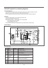
Tuning
The AFC information of the TDA8374 is not available as an analogue voltage.
Automatic following (=frequency tracking, AFC) can be done via the I2C-bus by software.
The TDA8374 AFC window is typically 80 kHz wide.
This value is made higher than the 62.5 kHz tuning step, to prevent an automatic following loop from continuously
adapting the tuning frequency..
With this AFC window ( 40 kHz) the maximum tuning error is less than 62.5 kHz.
For high speed search-tuning-algorithms, the AFC window can be widened to 240 kHz via bit AFW.