


32 33
QT5116
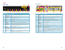
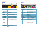
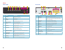
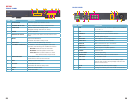
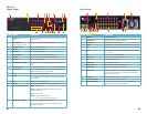
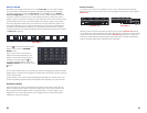
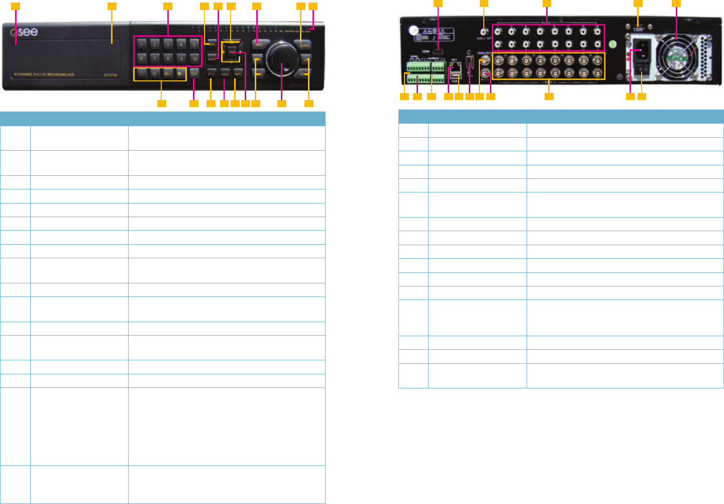
FRONT PANEL
ITEM NAME FUNCTION
1
POWER (Behind flip-down
panel)
Puts the DVR into standby mode or wakes it up from
standby mode.
2
USB PORT
(Behind flip-down panel)
Used for external USB backup devices.
3
NUMBER PAD Enter channel numbers.
4
MENU Opens the Main Menu
5
BACKUP Opens Backup Menu
6 DIRECTION Navigates through selections in menus
7 RECORD
Begins manually recording on all channels
8 SEARCH
Enters Search Mode
9
INDICATOR LIGHTS Shows status of the DVR Functions and the Hard
Drive
10 VIEWING MODE
Change between 1, 4, 8 and 16-screen viewing mode
11 10+ BUTTON
Input channels numbers above 10 by pushing this
button followed by the second digit.
12 PTZ
Enter PTZ mode in live view
13 AUDIO
Turn audio on or off in live view if audio input devices
are attached.
14 INFO
Displays system information
15 ENTER
Confirms selection in menus or input in fields
16 PLAYBACK CONTROLS
REW - Rewind
PLAY - Opens the Playback interface. Pauses or
resumes playback
FF - Fast Forward
STOP - Quits Playback mode
Also switches video output mode.
17
CONTROL KNOB Outer ring navigates through menus
Inner knob increases or decreases speed of fast
forward or rewind.
3 5 7
4
1
2 6
9
8
10 11 12 14 1613 1715 16
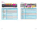
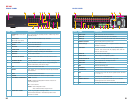
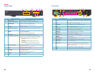
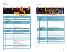
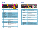
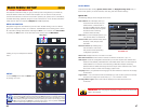
BACK PANEL
ITEM NAME FUNCTION
1 HDMI HDMI video output
2 AUDIO OUT Audio output for amplified speaker
3 AUDIO IN 16 channels of audio input
4 eSATA Connection for external eSATA hard drive for backup
5 FAN Cooling fan exhaust port. This should not be blocked.
6 PTZ Connections for Pan-Tilt-Zoom speed dome cameras.
Y = “+” Z = “-”
7 K/B Connector for a PTZ keyboard
8 ALARM IN Connect up to 16 external sensors
9 LAN Network (ethernet) port
10 USB PORT For the USB mouse
11 VGA PORT VGA output for 19” or larger monitor
12 VIDEO OUT BNC connector for TV or monitor
13 SPOT OUT Connect to another monitor as an auxiliary output
channel. This monitor will only display video and will
have no menu access.
14 VIDEO IN BNC connectors for up to 16 cameras
15 POWER SOCKET Attachment point for power cord
16 POWER SWITCH Use to turn on the DVR as well as to turn off after
powering down from within the GUI
3 51 2
4
6 87 9 10 11 15 161412 13