


10 11
You may view this DVR using a standard 19” (or larger) VGA monitor or a television. The
former is connected using the VGA port on the back panel while the television utilizes the
BNC “Video Out” port on the back. Your DVR is configured to use the VGA port as the main
display. To use a TV, you will need to press and hold the STOP/ESC, EXIT or VGA/TV button
(depending on model) for approximately 10 seconds until you hear a beep indicating that the
video mode has been switched. A display connected to the other port will not show the menu.
CONNECTIONS AND CONTROLS
CHAPTER 2
2.1 DVR FUNCTIONS AND CONNECTIONS
Search
Info
Backup Audio/+
P.T.Z/-
QT2124
REC HDD
Backup Net Play Power
1 3 54
8 9 10 11 12 13
72
Menu
6
SPOT
DC 12V
VIDEO OUT
VIDEO IN
1 3 5 7 9
2 4 6 8 10
11 13 15 17 19
12 14 16 18 20
21
22
23
1 2 3 4
24
VGA
NET USB
P/Z
Y Z A 1 3 5 7 9 1113 15
2 4 6 8 101214 16
B
ALARM OUT
ALARM IN
AUDIO IN
AUDIO OUT
K/B
GND
COM
NO
SV
31 54
7 98 11
1312
62
10
QT2124
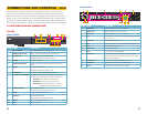
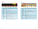
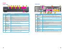
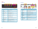
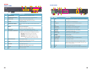
FRONT PANEL
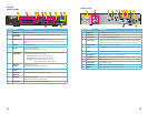
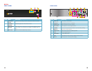
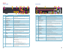
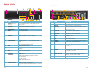
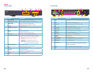
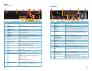
BACK PANEL
ITEM NAME FUNCTION
1 IR RECEIVER Receives signals from remote control
2 NUMBER BUTTONS Select individual channels for full screen view
3 DIRECTION Selects multi-screen viewing mode
Navigates through selections in menus
4 ENTER Confirm Selection
5 INDICATOR LIGHTS Shows status of the DVR Functions and the Hard
Drive
6 MENU Opens the Main Menu
Increases the value in Setup mode
7 USB PORT Used for external USB backup devices.
8 PLAYBACK CONTROLS In addition to normal DVR playback and record
operation, the following have additional functions:
RECORD Controls Focus in PTZ mode
REVERSE Controls Speed in PTZ mode
STOP/ESC Exits current interface or status
Also switches video output mode.
9 SEARCH/ZOOM Enter Search mode
Controls Zoom function in PTZ mode
10 INFO Displays system information
11 BACKUP Enter Backup mode
Decreases the value in Setup mode
12 AUDIO Mutes or unmutes audio
13 PTZ Enter PTZ mode
ITEM NAME FUNCTION
1 VGA PORT VGA output for 19” or larger monitor
2 VIDEO OUT BNC connector for TV or monitor
3 VIDEO IN BNC connectors for up to 24 cameras
4 PTZ Connections for Pan-Tilt-Zoom speed dome cameras.
Y = “+” Z = “-”
5 AUDIO IN 4 channels of audio input
6 FAN Cooling fan exhaust port. This should not be blocked.
7 NET Network (ethernet) port
8 USB PORT For the USB mouse
9 K/B Connector for a PTZ keyboard
10 SPOT OUT Connect to another monitor as an auxiliary output
channel. This monitor will only display video and will
have no menu access.
11 ALARM OUT 1 Channel relay output for external alarm
12 ALARM IN Connections for up to 16 external sensors
13 DC IN Power input for 12V DC power supply