


56 57
CHAPTER 7 ALARMS
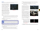
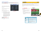
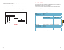
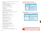
The accompanying diagram (Picture 7-2), along with your alarm’s manual should be
consulted to ensure proper connection.
• Normal open or Normal close type
• Parallel connect COM end and GND end of the alarm detector (Provide external power to
the alarm detector).
• Parallel connect the Ground of the combo DVR and the ground of the alarm detector.
• Connect the NC port of the alarm sensor to the combo DVR alarm input(ALARM)
• Use the same ground with that of combo DVR if you use external power to the alarm device.
PICTURE 7-2
+12V GND COM PC
GND
ALARM
Alarm input public end should jump out with device power end.
Alarm Device Connection Terminal
Alarm Device
Connection Terminal
+12V GND
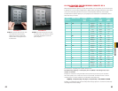
Relay Specification
Model: JRC-27F
Material of the contact Silver
Rating (Resistance Load) Rated switch capacity 30VDC 2A, 125VAC 1A
Maximum switch power 125VA 160W
Maximum switch voltage 250VAC, 220VDC
Maximum switch currency 1A
Insulation Between contacts with same polarity 1000VAC 1minute
Between contacts with different
polarity
1000VAC 1minute
Between contacts and winding 1000VAC 1minute
Surge voltage Between contacts with same polarity 1500V (10×160us)
Length of open time 3ms max
Length of close time 3ms max
Longevity Mechanical 50×106 times (3Hz)
Electrical 200×103 times (0.5Hz)
Temperature -40°C ~+70°C (-40°F to +158°F)
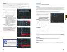
7.2 ALARM OUTPUT
The alarm output port should not be directly connected to a higher power load (greater than
1A) to avoid high current which may damage the relay. Use the co-contactor to establish the
connection between the alarm output port and the load.
• 2 way relay alarm output (NO contact). Provides external power to external alarm device.
• To avoid overloading, please read the following relay parameters sheet carefully.
• RS485 A/B cable is for the A/B cable of the PTZ camera.