


12 13
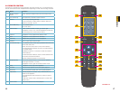
Mouse
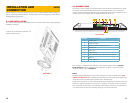
The included USB mouse will only operate if connected to the DVR through the USB port
on the rear of the DVR (Item number 8 in Picture 2-2). The USB port on the side of the
DVR’s screen is only for external USB storage devices.
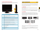
Cameras
Conventional CCD or CMOS cameras are
connected to the DVR through the Audio/
Video port (Item number 7 in Picture
2-2) via the A/V dongle included with the
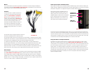
system. The dongle shown in Picture 2-3
has eight Video In plugs (black) for cameras
and four audio input plugs (yellow). The
extra black and yellow plugs are Video Out
and Audio Out respectively. The dongle
that comes with your DVR may differ in the
number of plugs depending on your DVR’s
features.
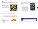
PICTURE 2-3
The cameras and the dongle use BNC connectors.
Each lead is identified with its channel number.
The cameras will also need to be connected to a power supply – whether the power supply
included with the cameras or a power distribution panel. For best results, both the DVR and
the camera power supply(ies) should share the same electrical grounding.
For cable runs longer than 200 feet, cable runs within walls, or in areas where there is
electromagnetic interference, you should use high-quality shielded RG59 cable. RG6 cable
should be used for runs exceeding 800 feet and fiber optic cable should be used when
distances exceed 1,800 feet. In circumstances requiring cameras to be positioned over 200
feet from the DVR, the camera’s power supply should be located closer to the camera.
Video Output
This DVR supports video output to two external monitors simultaneously through the HDMI
port (Item number 9 in Picture 2-2) along with the Video Out cable on the dongle. Use
of the HDMI output requires an HDMI cable (not included) along with a monitor or television
capable of processing 720i high-definition signals. The BNC Video Out lead on the dongle is
labeled as such. For output through the dongle, you will need to use a signal converter box to
connect to a VGA monitor or a television with VGA inputs.
Audio Input, Output and Bidirectional
Audio input and output is also handled through the BNC dongle. Each channel, including the
output channel, is labeled on the lead itself. To receive audio signals, you must have a camera
with built-in microphone or a separate microphone located near the camera.
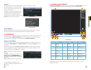
Normal output through the BNC audio out
channel is usually over 200mv 1KΩ. It can
directly connect to an active sound box or
amplified speaker. There is also an earphone
jack on the right side of the unit above the
USB port which allows you to listen to any
audio feeds without additional equipment.
The audio out lead can alternately be used to allow you to communicate with someone near
one of your cameras. This will require placing a powered speaker in the same location as that
camera. There also needs to be a microphone co-located with that camera if not built into the
camera itself. You will also need to connect a microphone to the microphone port on the side
of the DVR and use the headphone/speaker port to hear the audio feed.
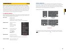
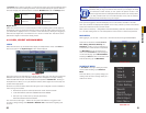
Using the DVR as a Computer Monitor
The DVR’s LCD screen can be used as a computer monitor by plugging in a VGA monitor
cable from a computer into the VGA In port (Item number 6 in Picture 2-2) on the back
of the system as you would with any regular computer monitor. This can be useful in the short
term when setting up network access of the DVR, or it can be a long-term solution such as
saving space or to hide the purpose of the DVR. You will not be able to use the screen to
view input from the computer and the cameras at the same time. External video input from a
computer will override the DVR’s video. You will need to install a monitor switch box between
the computer and the DVR to manually “turn off” the computer’s video feed, allowing the
system to display normally.
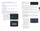
Headphone/
Speaker Port
Microphone
Port
USB Port
for Back-Up
PICTURE 2-4