


10 11
Please note that it is important to keep in mind common safety guidelines when installing your
DVR or connecting additional devices – including turning off and unplugging your DVR before
installing internal components.
2.1 DVR INSTALLATION
This DVR can be mounted on the included stand or it can be wall-mounted using a separately
available mounting kit.
INSTALLATION AND
CONNECTION
CHAPTER 2
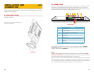
To attach the circular base to the DVR, use
the five included screws.
PICTURE 2-1
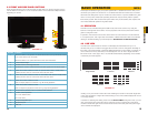
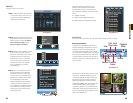
2.2 CONNECTIONS
As part of its compact design, the connection ports on this DVR are concentrated on a panel
on the back of the device located above the stand. These ports allow you to connect the
mouse, cameras and network cable along with additional input and output components such
as alarms, pan-tilt-zoom (PTZ) cameras, additional monitors and so on.
The connection, configuration and operation of PTZ cameras will be covered in Chapter
6 PTZ Cameras while the connection and configuration of alarms – both incoming and
outgoing – will be covered in Chapter 7.
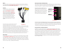
Power
The DVR’s power supply plugs into the socket marked DC 19V next to power switch (Item
number 2 in Picture 2-2). It is absolutely essential that you only use the power supply that
came with the DVR to ensure proper operation and to avoid damage.
We also recommend that you use an uninterrupted power supply (UPS) so that the system will
continue to operate in the event of a power loss. In addition, you should connect the DVR into
a UL-1449 rated surge protector. It should have a joule rating of at least 400, a response time
of 10 nanoseconds or less and a clamping voltage of no more than 330 volts.
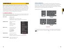
PICTURE 2-2
VGA AUDIO/VIDEO
USB HDMI
RS232
NET
DC 19V
NOC
1
NOC
2
1 2 3 4 5 6 7 8
AB
CNTRL
12V
1 2
8 9
3 4 5 76
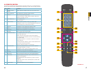
Number Function
1 Power button
2 Power input port
3 Alarm input/alarm output/RS485 port
4 Network port
5 RS232 port
6 VGA input port
7 Video and audio input, video and audio output
8 USB Port
9 HDMI Video Port