


Installation, cont’d
Digital Display Scaler • Installation2-4
5
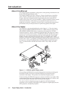
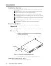
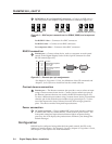
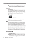
RGB/HD R-Y, B-Y, Y Output BNC connectors — Connect an RGB video or
HD component video display to these female BNC connectors (figure 2-4).
VH
RGBHV video
RGBS video
Component video (R-Y, B-Y, Y)
S
S
HV
R
/R-Y
G
/Y
B
/B-Y
R
/R-Y
G
/Y
B
/B-Y
VH
S
R
/R-Y
G
/Y
B
/B-Y
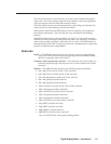
Figure 2-4 — BNC output connections for RGBHV, RGBS, and component
video
For RGBHV video — Connect to five BNC connectors.
For RGBS video — Connect to four BNC connectors.
For component video — Connect to three BNC connectors.
RS-232 connection
6
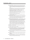
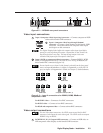
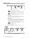
Remote port — Connect a host device, such as a computer or touch panel
control, to the Digital Display Scaler via this 9-pin D connector for serial
RS-232 control (figure 2-5).
Female
51
96
Male
15
69
RS-232 FunctionPin
1
2
3
4
5
6
7
8
9
—
TX
RX
—
Gnd
—
—
—
—
Contact closure, input #1
Transmit data
Receive data
Contact closure, input # 2
Signal ground
Not used
Not used
Not used
Not used
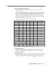
Figure 2-5 — Remote port pin assignments
See chapter 4, Programmer’s Guide, for definitions of the SIS commands and
chapter 5, Scaler Software to install and use the control software.
Contact closure connection
6
Remote port — The Remote connector also provides a way to select an input
using a remote contact closure device. Contact closure control uses pins on
the Remote connector that are not used by the RS-232 interface (figure 2-5).
To select a different input number using a contact closure device, momentarily
short the pin for the desired input number to logic ground (pin 5). To force
one of the inputs to be always selected, leave the short to logic ground in
place. The short overrides front panel input selections.
Power connection
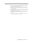
7
AC power connector — Plug a standard IEC power cord into this connector
to connect the scaler to a 100 to 240VAC, 50 Hz or 60 Hz power source. The
front panel control and input selection buttons light in sequence during
power-up, the LCD displays the product name and then cycles through the
default messages.
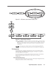
Configuration
DDS 402 can be configured using either the front panel controls, the SIS, or the
Windows Control program. See chapter 3, Operation, chapter 4, Programmer’s Guide,
and chapter 5, Scaler Software for more information.