


QS-1
Quick Start — DDS 402
Installation
Step 1
Turn off power to the DDS 402 and input and out-
put devices, and remove power cords from them.
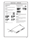
Step 2
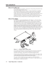
Install four rubber feet on the bottom of the
DDS 402, or mount the DDS to furniture or in a rack
(see figure on the bottom of this page).
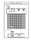
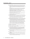
Step 3
Attach input devices to the DDS.
Input 1: RGB with buffered local
monitor
Input 2: RGB or component
video
R
/R-Y
G
/Y
B
/B-Y
R
/R-Y
G
/Y
B
/B-Y
H
/HV
V H
/HV
V
R
/R-Y
G
/Y
B
/B-Y
H
/HV
V
RGBHV video
RGBS video
RGsB video Component video (R-Y, B-Y, Y)
R
/R-Y
G
/Y
B
/B-Y
H
/HV
V
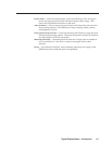
Step 4
Attach output devices to the DDS 402.
Rear panel video outputs
RGB or HDTV component video
output (15HD)
RGB or HDTV component video output (6 BNCs)
VH
RGBHV video
RGBS video
Component video (R-Y, B-Y, Y)
S
S
HV
R
/R-Y
G
/Y
B
/B-Y
R
/R-Y
G
/Y
B
/B-Y
VH
S
R
/R-Y
G
/Y
B
/B-Y
The two video output connectors, the 15HD
connector and the five BNC connectors, both
output the same video signal and the same
sync format.
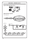
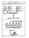
Step 5
Plug the DDS 402 and input and output devices
into a grounded AC source, and turn on the input
and output devices. The figure on the following
page shows a typical application.
Step 6
Use the LCD menu screens (see the next page) or
RS-232 programming to configure the DDS 402.
See chapter 2 for installation, chapter 3 for front
panel operation, and chapters 4 and 5 for
RS-232 operation.
RGB
1
RGB/R-Y, B-Y, Y
2A MAX
100-240V 50-60Hz
REMOTE
RGB/HD R-Y, B-Y, Y
RGB/R-Y, B-Y, Y
RGB
RGB/R-Y, B-Y, Y
21
R
/RY
G
/Y
B
/B-Y
H
V
S
R
/RY
G
/Y
B
/B-Y
H
V
S
O
U
T
P
U
T
S
I
N
P
U
T
S
Rack-mount
Bracket