


INSTALLATION
20 PNEG-1521 Commercial Direct Gear Drive Bin Sweep Auger
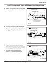
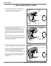
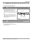
A. Attach the upper and lower Bin Flanges to the
Unload Tube Assembly using two (2) 5/16" x 1-½”
Hex bolts, and Serrated Flange nuts.
7. BIN FLANGE INSTALLATION
B. Install the Clutch Control Pipe Position Lock to the
lower Bin Flange using two (2) 5/16" x ¾”
Carriage bolts and Serrated Flange nuts. Install
the Carriage bolt heads on the backside of the
lower Bin Flange so they will be next to the Bin
Wall when the Bin Flanges are attached to the
Bin.
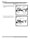
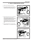
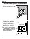
C. With the Bin Flanges not yet attached to the Bin
Wall, make sure that the Bin Wall opening is large
enough for the Clutch and Well Control Rods to
pass through the Bin Wall.
D. Slide the Bin Flanges flush up to the Bin Wall and
tighten the two bolts connecting the two Flanges.
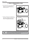
E. Drill into the Bin Wall through the holes located in
the four (4) corners of the Bin Flanges. Fasten
the Bin Flanges to the Bin Wall using four
(4) 5/16" x ¾” Bin bolts and Serrated Flange nuts.
F. Drill the remaining hole into the Bin Wall and attach
the remaining 5/16" x ¾” Bin bolt and Serrated
Flange nut.
Upper Bin
Flange
Lower Bin Flange
5/16” x 1-1/2”
Hex Bolt
5/16” Serrated
Flange Nut
5/16” Serrated
Flange Nuts
Clutch Control Pipe
Position Lock
5/16” x 3/4”
Carriage Bolts
5/16” x 3/4” Bin Bolt
5/16” Serrated
Flange Nut
FIG. 7-A
FIG. 7-B
FIG. 7-C