44 HP High-Definition LCD TV Service Manual
Removal Procedures
Included in this section are the following procedures and illustrations:
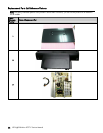
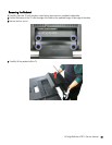
• Removing the TV Pedestal
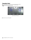
• Disassembling the Pedestal
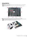
• Removing the Back Cover
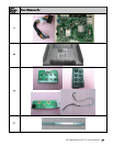
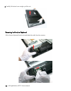
• Removing the Function Keyboard
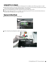
• Installing the Keyboard PCA
• Removing the Infrared Board
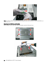
• Removing the Wall Mount Bracket
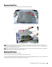
• Removing the Board Cover
• Removing the Main Board
• Removing the Power Supply
• Removing the Main Bracket
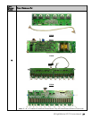
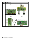
• Removing the Inverters
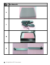
• Removing the Speakers
• Removing the Control Board
• Removing the Front Bezel
Removal Order
To remove the following components, you can remove the main bracket while leaving the main board and power
supply in place:
• Control board
• IR board
• Inverters
• Speakers
Screws
All screws in the TV are all Philips head of differing sizes, lengths, and threads.
As a general rule, screws that secure plastic components are self-tapping, while screws that secure metal components
are machine screws.
A repair screw kit (452128-001) containing a sampling of all screws is available.


