10
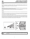
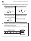
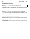
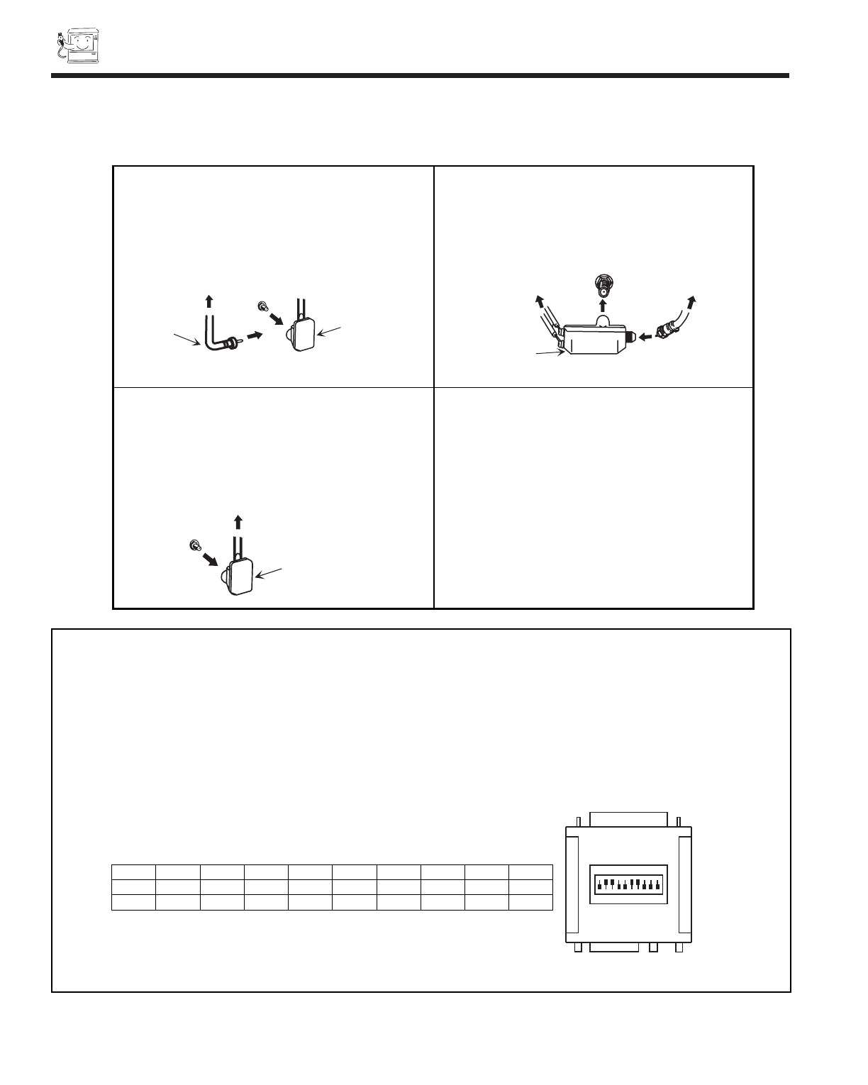
1. VHF (75-Ohm) antenna/CATV 3. When both VHF and UHF antennas are connected
When using a 75-Ohm coax
ial cable system, Attach an optional ANTENNA MIXER to the TV
disconnect the VHF adaptor from the VHF 75-Ohm antenna terminal and connect the cables to the
receptacle and connect the outdoor antenna or ANTENNA MIXER.
CATV cable to a VHF 75-Ohm receptacle.
2. VHF (300-Ohm) antenna/UHF antenna Notes:
When using a 300-Ohm twin lead from an outdoor 1. If an outdoor antenna/CATV is used, disconnect
antenna disconnect the (VHF or UHF) indoor the indoor antenna. Ghosting and poor reception
antenna leads from screws of the (VHF or UHF) may result if both the indoor and outdoor antennas/
adaptor and connect outdoor (VHF or UHF) CATV are connected at the same time.
leads to these screws of a (VHF or UHF) adaptor.
2. Consult your dealer or service store for the
ANTENNA MIXER and (VHF or UHF) adaptor.
3. The special converter (decoder) will be supplied
by
the cable company.
To outdoor antenna or CATV cable
VHF/UHF
75 Ohm
Coaxial Cable
(disconnect)
VHF Adaptor
ANTENNA
MIXER
VHF/UHF
To UHF Antenna
To outdoor
VHF Antenna
(Rear of TV set)
To outdoor VHF
or UHF Antenna
(connect)
VHF Adaptor
ANTENNA CONNECTIONS
These sets are equipped with one VHF/UHF antenna terminal. The VHF/UHF terminal can be used for normal TV, cable TV (CATV),
a TV game, etc.
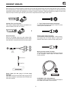
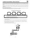
HOOKUP CABLES AND CONNECTORS
NOTE: Optional adapter for *Apple
®
Macintosh
®
computers. (*See page xx). If the optional AESP model G301/U Macintosh
to VGA
®
adapter connector is configured and connected between Macintosh video out and the 36SDX88B video in,
the Macintosh is forced to boot in 640 x 480/60 Hz or 800 x 600/60 Hz mode (set mode) because the operational
adapter correctly manipulates the Macintosh sense pins.
For the optional adapter to work, it s DIP switch settings should be # 2, 3, 6, 7 = ON and # 1, 4, 5, 8, 9, 10 = OFF.
See below: Example - See Switch Instructions for details.
Mode 5 = 2367 (SVGA 800 x 600/60 Hz configuration)
(VGA 640 x480/60 Hz configuration)
Composite Separate Sync
ON
DIP
1
2
3
4
5
6
7
8
9
10
ON
1
4
5
8
9
10
2
3
6
7
OFF
SW1 SW2 SW3 SW4 SW5 SW6 SW7 SW8 SW9 SW10
ON ON ON ON
OFF OFF OFF OFF OFF OFF
3. When both VHF and UHF antennas are connected
Attach an optional ANTENNA MIXER to the PC ready
color TV antenna terminal and connect the cables to
the ANTENNA MIXER.
(Rear of PC ready
color TV set)


