


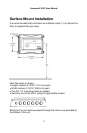
Honeywell 301C User Manual
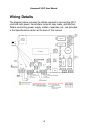
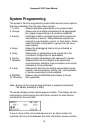
J22 Power Input: Connect the power supply to the controller
(see Wiring Details for cabling diagrams)
J23, J24 Communi-
cation inputs: Connect communication cables to channels 1
through 3.
Relay Outputs 1-4: Depending on the desired configuration,
connect the relay cables to either N.O. or N.C.
Relays 1 and 2 are commandable by either
internal events or by BACnet; relays 3 and 4
are driven only by internal events.
SHDN jumper Place the jumper over the Shutdown header
pins to reset or restart the system.
EOL Resistors 1-4: Place the jumper over the header pins to
include resistors to attenuate communication
echoes.
Power Connections
The 301C requires a power range of 17-27 Vac, 50/60 Hz (8.64 VA),
18-36 Vdc, 350 mA @24 Vdc (8.4 VA). Polarization is not important in
either AC or DC mode. The system must be grounded on the
transformer and a dedicated circuit breaker must be used.
Communication Connections
Communication cables must be grounded using the shield terminal,
using twisted and shielded pair Belden 2-24 AWG #9841 cable (or
equivalent).
The network cabling can extend up to a limit of 2000 feet (609 m) per
channel.
The length of a T-tap can reach 65 feet (20 m), up to a maximum of
130 feet (40 m) for all T-taps.
The 301C controller communicates with gas sensors over a Modbus
RS-485 network. This transmission line requires that 120Ω termination
resistors be fitted at both ends of each network segment to absorb the
13