


16
Recorder
BR-DV600
BR-DV600
BR-S800
SR-S365 (U MODEL)
SR-S388 (E MODEL)
BR-DV600
Player
BR-DV600
BR-DV600
BR-DV600
BR-DV600
BR-S800/BR-S500 (+ SA-N50)*
5
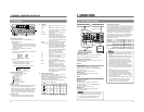
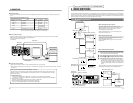
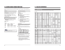
Edit adjust setting
The No. 353 <EDIT ADJUST> menu switch must be adjusted according to the configuration of the editing system being
used.
Setting table (when the RM-G800 is used)
Signal connection method
Analog
IEEE 1394
Analog
Analog
Analog
Setting
0 F
0 F
0 F
0 F
---
Setting
4 F
2 F
---
---
3 F
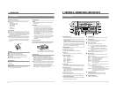
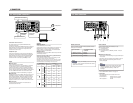
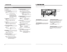
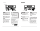
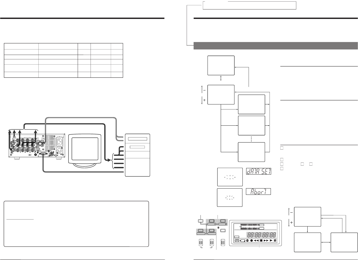
3 CONNECTIONS
DC 12V
PGZ01945
TIMER
TIME CODE
SPARE
COMPONENT
VIDEO
SYNC IN
REC
OFF
PLAY
DV
IN/OUT
REMOTE
AUDIO
2
1
SERIAL
CH 1/3
OUT
OUT
IN
IN
B-Y
IN
Y/C
LINE
OUT
OUT
MONITOR
CH 2/4
MONITOR
OUT
R-Y
Y
Video signal
Audio signal
Non-linear editing system
Remote control
5
Non-linear editing system
Material recorded on a MiniDV tape can be captured to a non-linear editing system. The following non-linear editing
systems are able to utilize Super Scene Finder (SSF) data.
• Canopus Corporation: DV Rex RT
• Casablanca
5
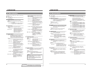
Control via the DV connector
• When the DV connector is used for control, assemble editing cannot be performed.
• When the VCR is stopped via the DV connector, a command error message may be returned to the controller. This is not
a malfunction.
Notes on connecting a cable to the [DV IN/OUT] connector
Set the following menu switches, turn the connected equipment ON and then connect the cable to the [DV
IN/OUT] connector. (If two BR-DV600s are connected to each other, it is not necessary to turn them ON.)
Menu switch settings
• When used as a player
Set the No. 108 <VIDEO INPUT SELECT> menu switch to any position except
“IEEE 1394”.
(If this switch is currently set to
“IEEE 1394”, change the setting and turn the power OFF and ON again.)
• When used as a recorder
Set the No. 108 <VIDEO INPUT SELECT> menu switch to
“IEEE 1394”.
• When controlled by another device via the [DV INPUT] connector
Set the No. 050 <REMOTE SELECT> menu switch to
“IEEE 1394”.
* To ensure the stability of input signals, install the SA-N50 in the BR-DV600.
17
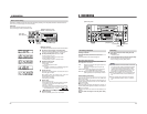
4 MENU SWITCHES
You can set menu switches using either the on-screen display or the counter display. To set switches on the on-screen display,
you will need to connect a monitor to the VCR
’
s [VIDEO MONITOR OUT] connector. This section explains how to set switches
using the on-screen display. The same procedures apply to switch setting on the counter display, the only difference being that
each menu switch item is indicated by numeric code rather than by name.
Menu switch group
select screen
03:SYNC SELECT
50:REMOTE SELECT
0
0
OFF
02 :OPERAT ION LOCK0
STOP
TCR 12:00:00:00
00~ : SYSTEM
00~ :TIMECODE
00~ : ONSCREEN
M:HOURMETER
3
4
5
H
00~ :AUDIO2
00~ : SERVO/ SYSTEM0
00~ :VIDEO1
[SELECT]
[MENU]
[SET]
[MENU]
[SHIFT]
UA
US+RS4 2
TO
2AJVC B
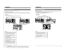
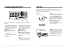
4-1 Menu switch organization
Menu switch group select screen
Pressing the [MENU] button with the normal screen
displayed brings up the menu switch group select screen.
Select the desired group with the [SHIFT +/
–] button.
The selected group number blinks.
Press the [SELECT] button to go to the selected group
menu switch setting screen.
Menu switch setting screen
To access this screen, press the [SELECT] button on the
menu switch group select screen.
Press the [MENU] button to go to the menu switch group
select screen.
Menu switch group select screen
Menu switch setting screen
On-screen display
LINE
08:VIDEO INPUT SELECT1
03:SYNC SELECT
UA
50:REMOTE SELECT
US+RS4 2
0
0
OFF
02 :OPERAT ION LOCK0
TO
2AJVC B
STOP
TCR 12:00:00:00
( HOUR ME TER )
H : DRUM HOUR METER
00000
D
0H
00 : SYSTEM
00 : TIME CODE
00 : ONSCREEN
M : HOUR ME TER
3
4
5
H
00 : AUDIO2
00 : SERVO/ SYSTEM0
00 : VIDEO1
[SET]
[MENU]
[SHIFT]
[SELECT]
[MENU]
Menu switch setting screen
On-screen display
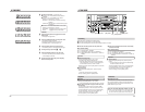
Switching the
setting screen
[SHIFT] +/–: Item select
SELECT: Changes the setting.
SET: Enters the setting.
Menu switch display
SHIFT
SET
SELECT
SHIFT
MENU
HOLD
AUDIO
MONITOR OUTPUT COUNTER
SHIFT A. DUB
ADVANCE PRESET
L CTL
TC
UB
CH-1/2
CH-3/4
R
MIX MIX
MENU
OVER
OVER
HMSF
AUD LOCK
32k 48k
PB NDF
SERVO RF
DEW
AUTO OFF
HOLD
CH 2/4
CH 1/3
dB40 30 20 10
0
DATA SET
ABORT
Counter display
When entered
When data has not
been entered yet
Menu switch setting procedure
Press the [SHIFT
–/+] button on the menu switch set-
ting screen to select the menu switch you want to set.
[The selected menu switch number blinks.
Press the [SELECT] button to change the set value.
Repeat steps
and
to change any other menu switches.
Press the [SET] button to end menu switch setting.
[The set value is entered and the normal screen is
restored. When entering the data, the indications shown
on the left are displayed. If data has not been entered
and menu switch setting is ended,
“Abort” indication is
shown.
To access another group menu switch setting screen without
ending menu switch setting, press the [MENU] button.
For servicing
See the service manual page 1-10 “1.6 SERVICE MENU”.
→