


26
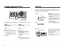
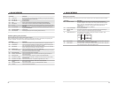
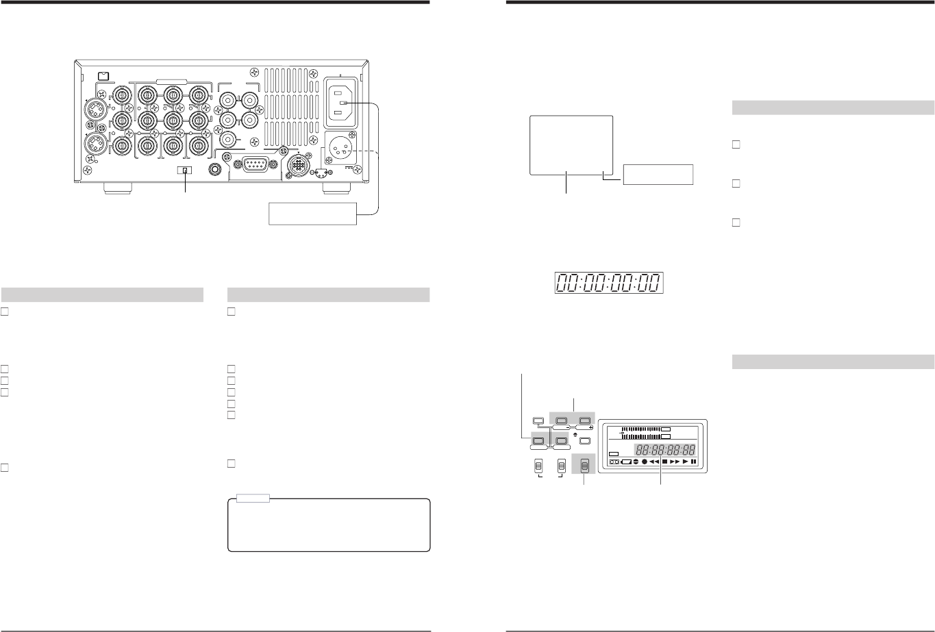
8 EXTERNAL TIMER-START FUNCTION
DC 12V
PGZ01945
TIMER
TIME CODE
SPARE
COMPONENT
VIDEO
SYNC IN
REC
OFF
PLAY
DV
IN/OUT
REMOTE
AUDIO
2
1
SERIAL
CH 1/3
OUT
OUT
IN
IN
B-Y
IN
Y/C
LINE
OUT
OUT
MONITOR
CH 2/4
MONITOR
OUT
R-Y
Y
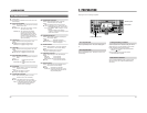
REC: Timer recording
OFF: Timer function OFF
PLAY: Timer playback
Commercially available
timer, etc.
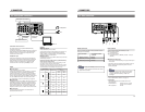
Playback
Connect the power cable.
To turn this unit ON with a commercially available timer,
connect the power cable plug to the timer’s power output
socket.
Set the front panel
’
s [REMOTE/LOCAL] switch to
“LOCAL”.
Insert a cassette.
Set the rear panel
’
s [TIMER] switch to “PLAY”.
When power is supplied, playback starts automati-
cally.
Repeat playback can be set with menu switch setting.
੬
See No. <311 AUTO PLAY> and No. 312 <AUTO
REW> on page 19.
With the menu switches set appropriately, the tape can
be rewound to the beginning before starting playback.
੬
See No. 360 <AUTO REW AT TIMER> on page 19.
Stop playback.
Press the [STOP] button.
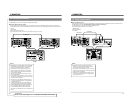
Recording
Connect the power cable.
To turn this unit ON with a commercially available timer,
connect the power cable plug to the timer’s power output
socket.
Set the front panel
’
s [REMOTE/LOCAL] switch to
“LOCAL”.
Select the video input.
Adjust the audio recording level.
Insert a cassette.
Set the rear panel
’
s [TIMER] switch to “REC”.
When power is supplied, the VCR automatically
enters the Record mode.
Using the menu switches, you can set the VCR to start
recording after rewinding the tape to the beginning.
੬
See No. 360 <AUTO REW AT TIMER> on page 19.
Stop recording.
Press the [STOP] button.
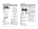
(AUTOMATIC START-UP WITH POWER SUPPLY)
When power (AC 120 V (U MODEL), AC 220 – 240 V (E MODEL) or DC 12 V) is supplied to this unit, it automatically enters
the Record or Play mode. Using a commercially available timer, you can configure your VCR to start recording or playback at a
specified time.
Note:
5External timer control should only be used to start
VCR operation. Do not use an external timer to turn
the VCR power off while the tape is running. Doing
so could damage this unit or the tape.
27
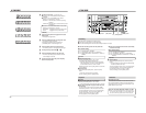
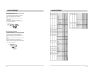
STOP
TCR 12:00:00:00
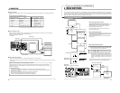
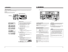
9 TIME CODE
The time code is recorded frame by frame together with the materials to be recorded on the tape.
With this time code, the position of the materials can be precisely specified, improving the editing accuracy and working
efficiency.
(The editing accuracy of 0 frame may not be obtained even though the time code is used, depending on the performance of
the VCR and editing controller and influence of editing system.)
With this system, the time code can be recorded and played back.
Display
Time code can be shown on the counter display and on the
on-screen display during playback and recording.
To display time code data on the on-screen display,
set the No. 514 <TIME DISPLAY SELECT> menu
switch to “TC”.
੬
See No. 514 <TIME DISPLAY SELECT> on page 20.
To display time code data on the counter display, set
the No. 516 <DISPLAY SELECT> menu switch to
“TC”.
੬
See No. 516 <DISPLAY SELECT> on page 20.
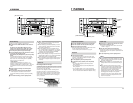
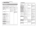
Set the [COUNTER] switch to
“TC” or “UB”.
TC: Shows the time code data display.
UB: Shows the user bits display.
All time code data including time code generator/reader,
drop/non-drop frame (U MODEL), CTL interpolation, etc.
are shown on the on-screen display
On-screen display
TCR: Time code reader data
TCG: Time code generator data
UBR: User bits reader data
UBG: User bits generator data
SP
SLAVE
SHIFT
SET
SELECT
SHIFT
MENU
HOLD
AUDIO
MONITOR OUTPUT COUNTER
SHIFT A. DUB
ADVANCE PRESET
L CTL
TC
UB
CH-1/2
CH-3/4
R
MIX MIX
MENU
OVER
OVER
HMSF
AUD LOCK
32k 48k
PB NDF
SERVO RF
DEW
AUTO OFF
HOLD
CH 2/4
CH 1/3
dB40 30 20 10
0
ADVANCE: Changes the value.
PRESET: Enters the set value.
Time code/user bits display
TC: Time code
UB: User bits
HOLD: Start
SHIFT: Moves the cursor to the next digit.
Preset
To give you more control over your material in editing and
recording, you can specify a preset time code value while
referring to the counter display indications. Determine the
required time code value beforehand.
• Set the [COUNTER] switch to
“TC” so that the counter
display shows the time code.
• Set the [COUNTER] switch to
“UB” to show the user bits
on the counter display.
Time code presetting is described below. The same
procedure is used to preset the user bits, except that user
bit values are hexadecimal (0 to F ).
HMSF
Counter display
: — Non-drop frame
· — Drop frame
(U MODEL)