


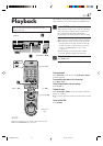

EN 43
R
Y
L
P
B
/C
B
VIDEO
P
R
/C
R
S VIDEO S VIDEO
AUDIO
R
IN
(L-1)
IN(L-2)
L
(MONO)
VIDEO
REMOTE PAUSE/
AV COMPULINK
CABLE BOX
ANTENNA
AUDIO
OUT
OUT
OUT
TV
IN
VHF/UHF
IN
DVB-ASI
IN
SYNC
POL
AC120V 1A G
–
+
Matching
Transformer
(not supplied)
AC Power
Cord
Audio Cable
(supplied)
TV
ANTENNA IN
(Antenna or cable input)
Back of
VCR
AC Outlet
Antenna or Cable
Flat Feeder
Coaxial Cable
AUDIO
OUT
To Audio
Input
Connectors
RF Cable
(supplied)
To 75 Ω termninal
TV OUT
Video Cable
(not supplied)
To Video
Input
Connectors
VIDEO OUT
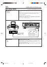
Connection
And
Preparation
ENCODER
AC Power
Cord
(supplied)
AC
Outlet
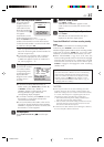
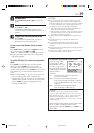
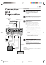
Connection
1
Check contents
Make sure the package contains all of the
accessories listed in “SPECIFICATIONS”
(੬ pg. 75).
2
Situate VCR
Place the VCR on a stable, horizontal surface.
3
Connect VCR to TV
The following connections are required.
1 Disconnect the TV antenna from the TV.
2 Connect the TV antenna cable to the
ANTENNA IN terminal on the rear of the
VCR.
3 Connect the supplied RF cable between the
TV OUT terminal on the rear of the VCR and
the TV’s antenna input terminal.
4 Connect an audio/video cable between the
AUDIO/VIDEO OUT connectors on the rear of
the VCR and the audio/video input connectors
on the TV.
5 Connect the not supplied BNC cabel between
the DVB-ASI IN terminal on the rear of the VCR
and the ENCODER’s output terminal.
4
Connect VCR to power source
Connect the supplied AC power cord to the AC In
connector.
Connect the AC power plug to the AC outlet.
● Please ensure connection of the supplied AC
power cord.
BNC cable
(not supplied)
AC IN
NOTE:
Before connection of the AC power cord, please reed the safety
information. (
੬
pg.3)
VDA300U-EN42-49 03.7.18, 12:15 PM43