


EN 71
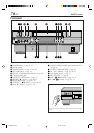
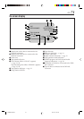
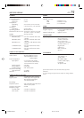
Rear panel
1 AC power cord : ੬ pg. 7
2 Cooling fan
● This prevents the temperature from rising inside the
VCR. Do not remove it.
● Install the VCR so as not to block the area around
the cooling fan.
3 Component video output connectors : ੬ pg. 8
4 S VIDEO/AUDIO/VIDEO IN connectors (L-1):
੬ pg. 58
5 JLIP terminal : ੬ pg. 55
6 CABLE BOX Controller connector :
੬ pg. 15, 18
7 ANTENNA IN terminal : ੬ pg. 7
8 DIGITAL OUT (OPTICAL) connector : ੬ pg. 50
9 AC IN connector : ੬ pg. 43
0 Fuse socket
! Ground terminal
@ S VIDEO/AUDIO/VIDEO OUT connectors :
੬ pg. 8, 58
# S VIDEO/AUDIO/VIDEO IN connectors (L-2):
੬ pg. 58
$ REMOTE PAUSE/AV COMPULINK terminal
● REMOTE PAUSE terminal : ੬ pg. 56
● AV COMPULINK terminal : ੬ pg. 53
% TV OUT terminal : ੬ pg. 7
^ DVB-ASI IN terminal : ੬ pg. 43
& SYNC POL switch
● This switch is usually set to a + (lower) side.
R
Y
L
P
B
/C
B
VIDEO
P
R
/C
R
S VIDEO S VIDEO
AUDIO
R
IN
(L-1)
IN(L-2)
L
(MONO)
VIDEO
REMOTE PAUSE/
AV COMPULINK
CABLE BOX
ANTENNA
AUDIO
OUT
OUT
OUT
TV
IN
VHF/UHF
IN
DVB-ASI
IN
SYNC
POL
–
+
AC120V 1A G
24
%$#
@9 0 ^ &!
56
3
7
8
1
VDA300U-EN64-79 03.7.18, 12:14 PM71