


49
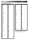
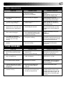
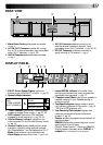
REAR VIEW
AV1 IN / OUT
AV2 IN
RF OUT
ANT. IN
32
4
5
1
4 AV2 IN Connector enables connection of
satellite receiver or second recorder; input
recordable when "AU 2" selected. ੬ pg. 30, 28
5 RF OUT Connector enables connection to
aerial terminal of TV receiver. ੬ pg. 4
1 Mains Power Cord supplies power to recorder.
੬ pg. 4
2 AV1 IN/OUT Connector enables AV connec-
tion to TV or second recorder; input recordable
when "AU-1" selected. ੬ pg. 4, 28
3 ANT. IN Connector enables connection of aerial.
੬ pg. 4
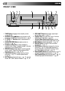
DISPLAY PANEL
SPLPEP
REVIEW
REMAIN
M
1 3 4 5
2
!
8 0
9
6 7
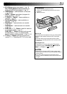
1 B.E.S.T. Picture System Display lights from
bottom to top while B.E.S.T. is active. ੬ pg. 20
2 Symbolic Mode Indicators
3 "Timer" Indicator lights when TIMER has been
pressed to engage Timer mode. ੬ pg. 23, 25
4 PDC Indicator lights when PDC has been
engaged for timer recording. ੬ pg. 22, 24
5 Counter Memory Indicator lights when the
video recorder is in the Counter Memory mode.
੬ pg. 15
6 Channel Display shows preset position where
the station currently being received is stored.
(Ex.) Preset position 1 will be displayed as "CH 1".
Mode shows external input mode selected.
Clock Display shows current time. ੬ pg. 9, 42
7 Instant REVIEW Indicator blinks after timer-
recording and shows how many programmes
have been timer-recorded. ੬ pg. 14
8 "Cassette Loaded" Mark lights once a cassette is
inserted; remains lit until cassette ejected or
power turned off.
9 Tape Speed Indicators display mode of record-
ing; light during Record or Play mode. ੬ pg. 18
* EP is for NTSC playback only.
0 Tape Remaining Time Indicator displays time
remaining on tape when certain buttons are
pressed. ੬ pg. 19
! Counter shows time elapsed since playback or
recording began.
REMAIN displays time remaining from current
tape position to end of tape.
Counter, Preset Position*, Clock and REMAIN
Display appear alternately when DISPLAY is
pressed.
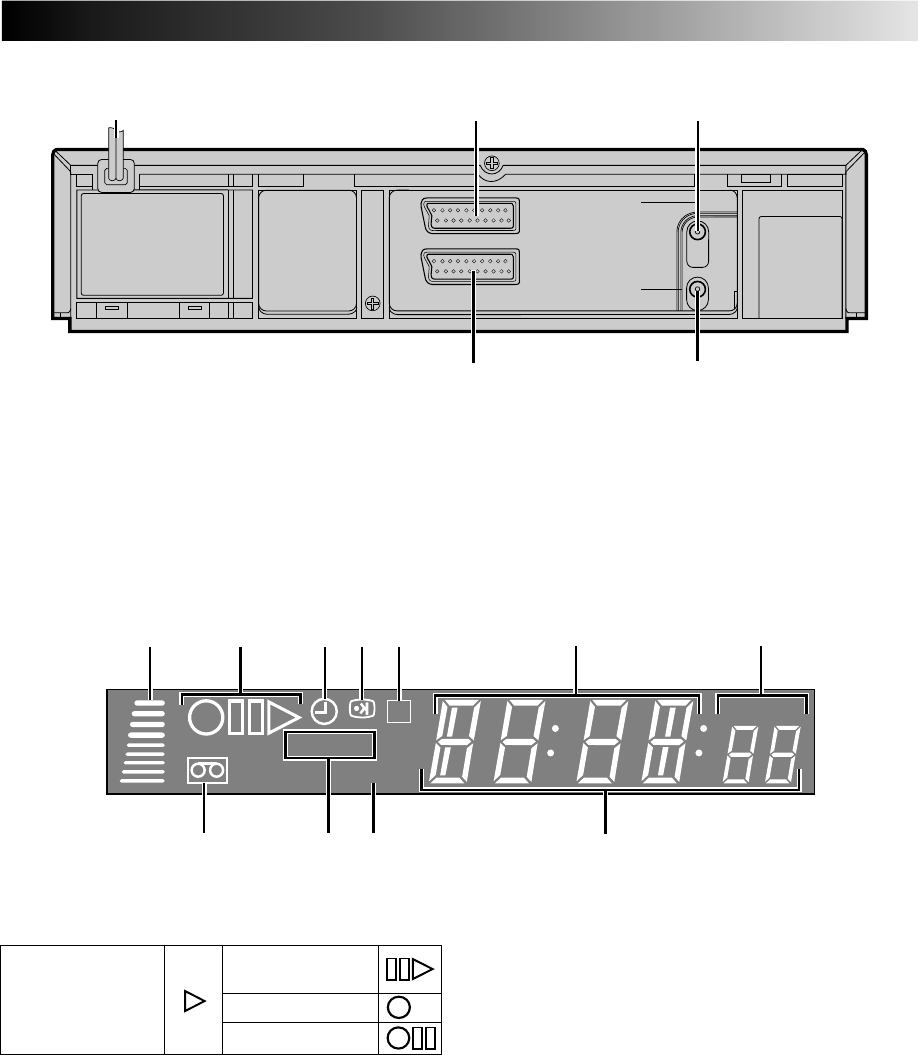
STILL:
SLOW:
RECORD:
RECORD PAUSE:
PLAY:
FF/REW VARIABLE
SHUTTLE SEARCH:
* Preset Position is not displayed during playback.