


11
Preparation
The following operations are possible with this system.
● Surveillance (live image, recording and playback) by connecting up to 16 cameras
● Checking recorded images on the VGA monitor
● Recording/Playing sound
● Alarm recording
● Remote surveillance using PCs
Memo :
● Connect LAN1 to the camera network.
● LAN2 to the surveillance computer network.
● For details of the protocol and port number for the network
cameras on the LAN1 network, refer to the network
camera’s user manual.
● The protocol and port number used on the LAN2 network
are shown below.
● Surveillance computer: HTTP 80
● Mail: SMTP 25/POP 110
● Connect NAS to the LAN1 network.
Note :
● Connect only after having turned AOFFB the power of all
devices.
● Set the IP address of the camera to 192.168.0.xxx. When
setting the IP address of the camera to an address other
than 192.168.0.xxx, you must also change the IP address
of LAN1. Refer to the [Instruction Manual] of each camera
for procedures to change the camera’s IP address,
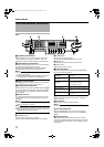
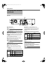
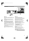
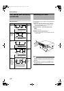
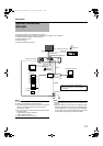
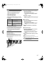
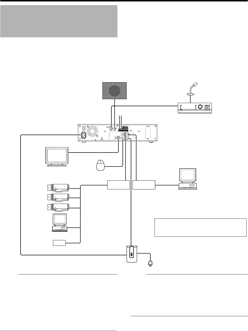
System Connection
Example
ON
OFF
AUDIO IN
AUDIO OUT
ALARM IN/ALARM OUT
VGA OUT
SERIAL
LAN1
LAN2
SERIAL
● You can connect up to 16 cameras.
● You can connect up to 10 surveillance
computers.
Speaker (with built-in amplifier)
ALARM IN/OUT
Supplied power cable
Mic Amp
VGA monitor
IP cameras
Computer for configuring
cameras
USB Mouse
Switching
HUB
Switching
HUB
UPS control
UPS
Microphone
Surveillance computer
NAS
VR-N1600_Startup_EN_001B.book Page 11 Thursday, August 20, 2009 1:10 PM