INSTALLATION
11
Connections (Continued)
Display Formats Overview
• The HDTV Tuner offers various display formats and multiple video outputs. If the HDTV Tuner is connected to A/V
systems, the HDTV Tuner can provide video signal formats 1080i, 720p, 480p, and 480i.
• 1080i, 720p, 480p, and 480i modes are available for component video (YPbPr) outputs.
• 1080i, 720p, and 480p modes are available for RGB and DVI outputs.
• 480i mode is available for VIDEO, S-VIDEO, and COMPONENT VIDEO outputs.
• The HDTV Tuner has two digital audio outputs; Dolby Digital 5.1 and PCM. The HDTV Tuner sends out a digital
audio signal to OPTICAL and COAXIAL audio outputs if digital broadcasts are being received by the HDTV Tuner.
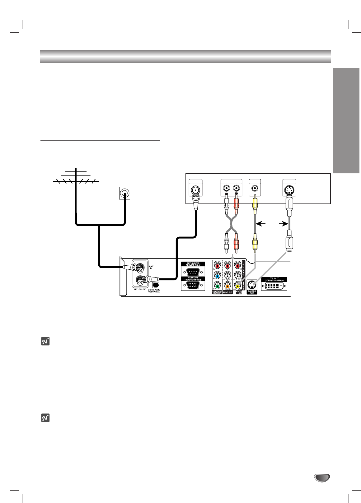
Analog Monitor Connections
11
Connect the “Antenna/Cable” to the “ANT IN” jack on the HDTV Receiver using a coaxial RF cable.
ote
There might be some areas where the signal strength could be too high. If so, you may need to connect the
antenna to an attenuator. Screw the attenuator onto the “ANT IN” jack. (Refer to page 10.)
22
Connect the “ANT LOOP OUT” jack from the HDTV Receiver to the “Antenna In” jack on your TV using a coaxi-
al RF cable.
33
Connect the “AUDIO OUT” and “VIDEO OUT (MONITOR OUT)” jacks from the HDTV Receiver to the “A/V IN”
jacks on your TV using RCA-type cables. If your TV is equipped with an S-Video jack, use the S-VIDEO OUT
jack.
(The Output Selection must be set to YPbPr, refer to Display Format Setup on page 17.)
ote
On-Screen display and Menus are only seen on these connections if the display format settings are set to 480i and
YPbPr. (Refer to page 17.)
Cable TV
Wall Jack Panel
OR
OR
L
R
AUDIO INPUT
L
VIDEO
INPUT
S-VIDEO
INPUT
ANTENNA
INPUT
TV Connection Panel
HDTV Receiver Connection Panel
Antenna
To AUDIO OUT


