


L200 Series - Back
12
L200 Series - Back
1 2 3 4
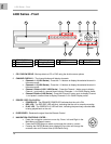
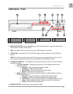
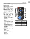
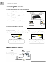
1. ETHERNET CONNECTION – Connects the DVR to a router for connection to the Local Network
and Internet.
2. VGA VIDEO OUTPUT – Video Output port to connect the unit to a Computer Monitor. Directly
reflects the current onscreen images.
3. BNC VIDEO OUT (1 & 2) – Video Output ports to connect the unit to the video input of a TV or
Observation System. Directly reflects the current onscreen images.
4. RCA AUDIO OUT / IN PORTS – Connection ports for Audio:
• AUDIO OUT - Audio Output port to connect the unit to a TV or Observation System.
• AUDIO IN - Connect One Audio input device such as a microphone to record Audio on
one channel.
5. BNC VIDEO INPUTS – Channel 1~4 (L204 Series) -or- Channel 1~8 (L208 Series) camera inputs
(used to connect Cameras with BNC connection type). Cameras with BNC connections require an
additional power adapter.
6. PS/2 PORT – Connection port for a PS/2 type mouse.
7. ALARM FUNCTION TERMINALS (INPUT/OUTPUT) - These terminals are used to connect external
alarm devices such as motion sensors or door/alarm sensors. Refer to appendix # for Alarm Block
Configuration.
8. RS-485 / PTZ CAMERA TERMINALS - These terminals are used to control PTZ (Pan/Tilt/Zoom)
type cameras. Refer to appendix # for PTZ Configuration
9. POWER INPUT – Connect to the DVR Power using the power cord provided with the unit. The
power cable connects the DVR to an electrical outlet.
10. POWER SWITCH – Turns the DVR ON or OFF.
5 6 7 8 9 10
1 LAN Port 4 Audio IN/OUT 7 Alarm Block 9 Power Input
2 VGA Port 5 Video IN 8 RS-485/PTZ Block 10 Power Switch
3 Video OUT 6 PS/2 Port