


!
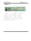
64
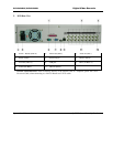
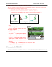
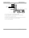
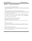
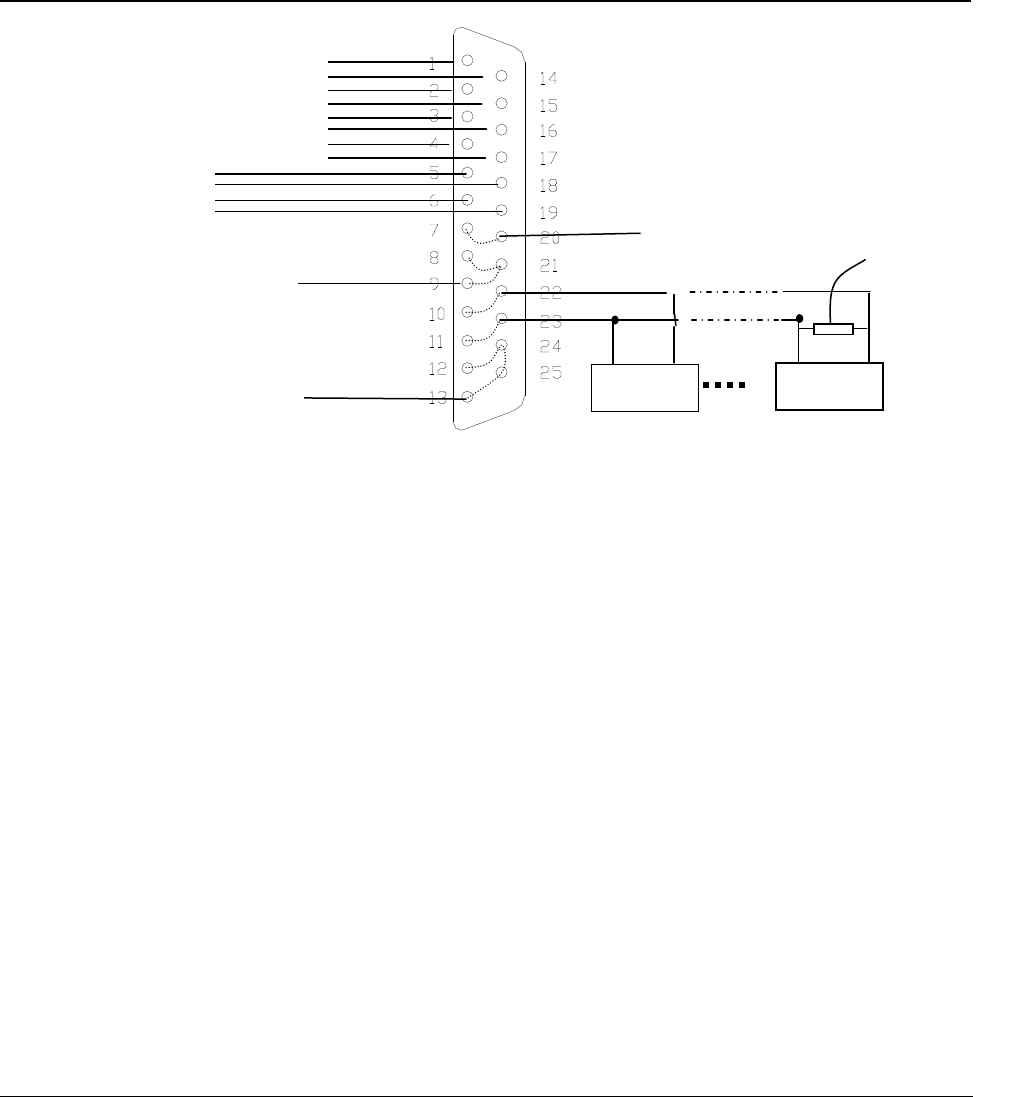
a) Pins 1,14,2,15,3,16,4,17 connects to alarm input: ALARM1~ALARM8
b) Pins 5 & 18 = OUTPUT Relay 1 - 6 & 19 = OUTPUT Relay 2 Each Relay (normally open):
c) Pins 7&20 = OUTPUT 3 is a controllable +12V output.
d) Pins 8, 9 & 21 are +12V power output, Use for Low current items only such as Relays and Alarm Devices.
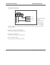
e) Pins 10 & 22 are the B line of RS485, Pins 11 & 23 are the A line of RS485;
f) Pins 12, 13, 24 & 25 are Ground (Gnd).
Combined as RS485 B line
Combined as RS485 A line
Decoder
Decoder
A B
A B
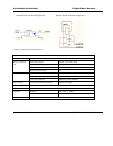
Alarm input ALARM 1
ALARM 8
Alarm output
ALARMOUT1
ALARMOUT2
Controllable +12V output
+12V output
Gnd
120 End of Line
(EOL) resister
required.