


8
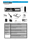
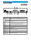
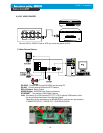
CHAP. 2 Function of Each Button
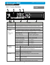
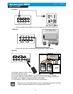
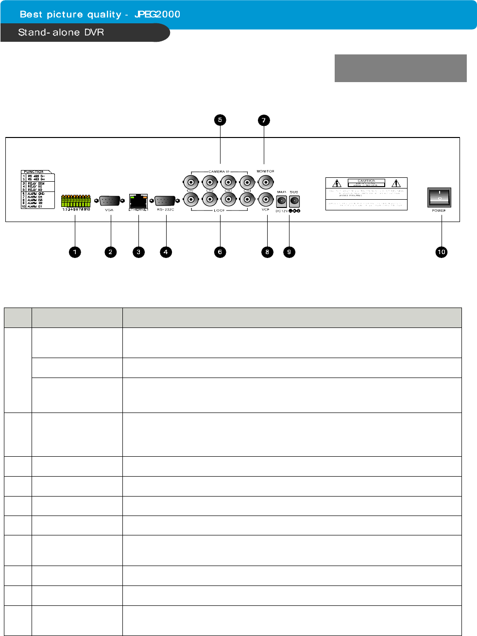
2-2. REAR
Name Function
RS 485
Connection with PTZ Camera or other external device using RS 485
interface
1
2
3
4
5
6
7
8
9
10
SENSOR Input
VGA
ETHERNET
RS-232C
CAMERA Input
LOOP Output
MONITOR
Output
RELAY Output Relay out terminal
Sensor input terminal
Connection to VGA Monitor (CRT type or TFT LCD monitor)
Just in case you purchased DVR with VGA option board fixed on the main
board of DVR, you can connect VGA Monitor to DVR unit.
Connection to ETHERNET device
Connection to external device as PC using RS-232C to control the DVR
Connection with camera
Camera loop out
Connection with Composite Monitor
VCR Output Connection with VCR for analog backup
DC Power
POWER
SWITCH
DC 12V 5A Adaptor (Refer to the Instruction for adapter by HDDs capacity)
Power ON/OFF switch for adapters