


8
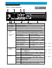
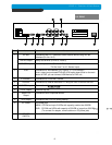
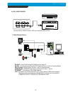
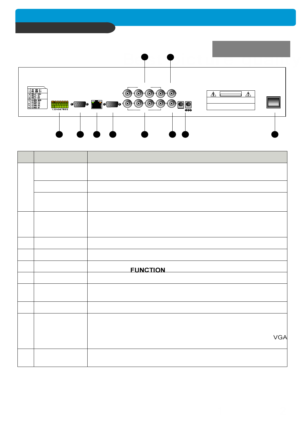
Name Function
RS 485 Connection with PTZ Camera or other external device using RS 485
interface (Pin No.1 & 2)
1
2
3
4
5
6
7
8
9
10
SENSOR Input
VGA
ETHERNET
RS-232C
CAMERA Input
LOOP Output
MONITOR
Output
RELAY Output Relay out terminal (Pin No.3, 4 and 5)
Sensor input terminal(Pin No.6 : Ground,
Pin No. from 7 to 10 : Sensor input)
Connection to VGA Monitor (CRT type or TFT LCD monitor)
Just in case you purchased DVR with VGA option board fixed on the main
board of DVR, you can connect VGA Monitor to DVR unit.
Connection to ETHERNET device
Connection to external device as PC using RS-232C to control the DVR
Connection with camera
Camera loop out
Connection with Composite Monitor
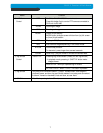
VCR Output Connection with VCR for analog backup
DC Power
POWER
SWITCH
DC power jack
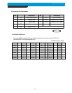
MAIN : CD-RW and up to 2 HDDs with capacity smaller than 200GB
SUB : CD-RW and HDDs with capacity of 200 GB or larger than 200 GB.
(To connect 2
nd
adapter, remove sticker on DC power jack)
Power ON/OFF switch for adapters
CHAP. 2 Function of Each Button
2-2. REAR