7 - 5
7 DATA LINK PROCEDURE
MELSEC-QnA
No. Name Description
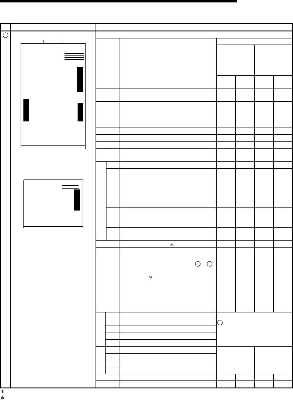
Data-link status can be checked from the LED on status.
LED display status
x Master station
x Standby master
station in
controlling the
system
x Local station
x Standby master
station on
standby
LED
name
Description
When
normal
When
error
When
normal
When
error
RUN
ON: Module is normal.
OFF: Watchdog timer error.
On Off On Off
ERR.
Indicates the communication status with the
station set in the parameter.
ON: Communication error at all stations.
Flashing: Communication faulty station exists.
Off
On or
flashing
Off
On or
flashing
MST ON: Set as a master station. On – Off –
S MST ON: Set as a standby master station. (On) – (On) –
LOCAL ON: Set as a local station. Off – On –
CPU R/W
ON: Communicating with programmable
controller CPU. (FROM/TO)
On Off On Off
SW ON: Switch setting error Off On Off On
M/S
ON: Master station already exists on the
same line.
Flashing: Occupied station count overlapping
(With the exception of the first
station number overlapping)
Off
On or
flashing
– –
PRM ON: Parameter setting error. Off On – –
TIME
ON: Cable disconnection, or no response
from all stations due to noise in a
communication path
Off On – –
ERROR
LINE
ON: Cable disconnection, or transmission
path is affected by noise, etc.
Off On Off On
L RUN ON: In data link. (host) 1 On Off On Off
L ERR.
ON: Communication error (host)
Flashing at regular intervals:
The setting(s) of switches
2
to
5
was changed while the power was
on.
2
Flashing at irregular intervals:
Terminating resistor is not
connected, or module and/or CC-
Link dedicated cable is affected by
noise.
Off
On or
flashing
Off
On or
flashing
156K ON: Transmission speed is set to "156 kbps"
625K ON: Transmission speed is set to "625 kbps"
2.5M ON: Transmission speed is set to "2.5 Mbps"
5M ON: Transmission speed is set to "5 Mbps"
BRATE
10M ON: Transmission speed is set to "10 Mbps"
4
Transmission speed set by the
transmission speed setting switch
is turned on.
TEST ON: Offline test in progress
S0
S1
TEST
S2
(Not used)
Refer to
Sections 7.4 and
7.8.
Refer to Section
7.4.
SD ON: Sending data On Off On Off
1
LED display
A
1SJ61QBT11
RUN
ERR.
MST
S MST
LOCAL
CPU R / W
L RUN
L ERR.
SD
RD
SW
M / S
PRM
TIME
LINE
E
R
R
O
R
A
J61QBT11
E
R
R
O
R
R
A
T
E
B
T
E
S
T
RUN
ERR.
MST
S MST
LOCAL
CPU R / W
SW
M / S
PRM
TIME
LINE
L RUN
L ERR.
156K
625K
2. 5M
5M
10M
TEST
S0
S1
S2
SD
RD
RD ON: Receiving data On Off On Off
1 When the module is operated in the synchronous mode, the LED may be lit dimly.
2 When all stations are in error, changes on switches may not be detected.


