


18
CHAPTER 2 PART NAMES
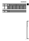
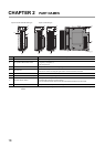
*1 Operate the Indication selector switch with your fingers. Do not use a screwdriver or similar tool as it may damage the
switch.
No. Name Description
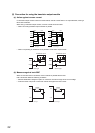
1) Module joint levers Levers for connecting two modules
2) I/O operation status indicator LEDs
Indicate the I/O status.
• On (green): I/O signal is on.
• Off: I/O signal is off.
3) Terminal block A 18-point terminal block for connecting I/O signal cables to external devices
4) Terminal cover
A cover for preventing electric shock
A label on it is used for recording the signal names of devices allocated to terminals.
5) DIN rail hook A hook used to mount the module to a DIN rail
6) Connectors for external devices (40 pins) A connector for connecting I/O signal cables to external devices.
7)
Indication selector switch
*1
• For input module or output module: Used to switch the LED indications between the first-half 32 points
and latter-half 32 points of a 64-point module.
• For I/O combined module: Used to switch the LED indications between input and output.
8) Serial number display Displays the serial number printed on the rating plate.
1)1)
2) 2)
1)
7)
6)
3)
4)
5)
1)
8)
2)
1)
6)
8)
8)
40-pin connector type18-point screw terminal block type