


43
CHAPTER 4 SPECIFICATIONS
4
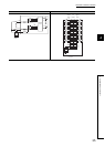
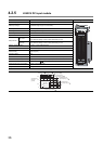
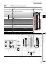
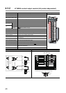
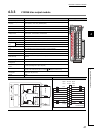
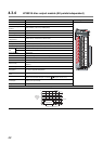
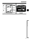
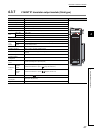
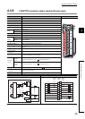
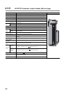
4.3 Output Module Specifications
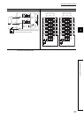
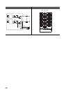
External connections Terminal connections
Load
Load
TB15
LED
TB16
100 to 240VAC
100 to 240VAC
LED
TB1
Internal
circuit
TB2
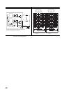
1
3
5
7
9
11
13
15
17
2
4
6
8
10
12
14
16
18
Y00
Y01
Y02
Y03
Y04
Y05
Y06
Y07
Y00
Y01
Y02
Y03
Y04
Y05
Y06
Y07
Empty
Empty
Signal
name
Signal
name
Terminal
number
External load power supply
External load power supply
External load power supply
External load power supply
External load power supply
External load power supply
External load power supply
External load power supply
Load
Load
Load
Load
Load
Load
Load
Load
The following diagram shows the external load power supply.
Viewed from the front of the module.
100 to 240VAC