77
CHAPTER 8 TROUBLESHOOTING
8
8.2 Troubleshooting for Output Circuit
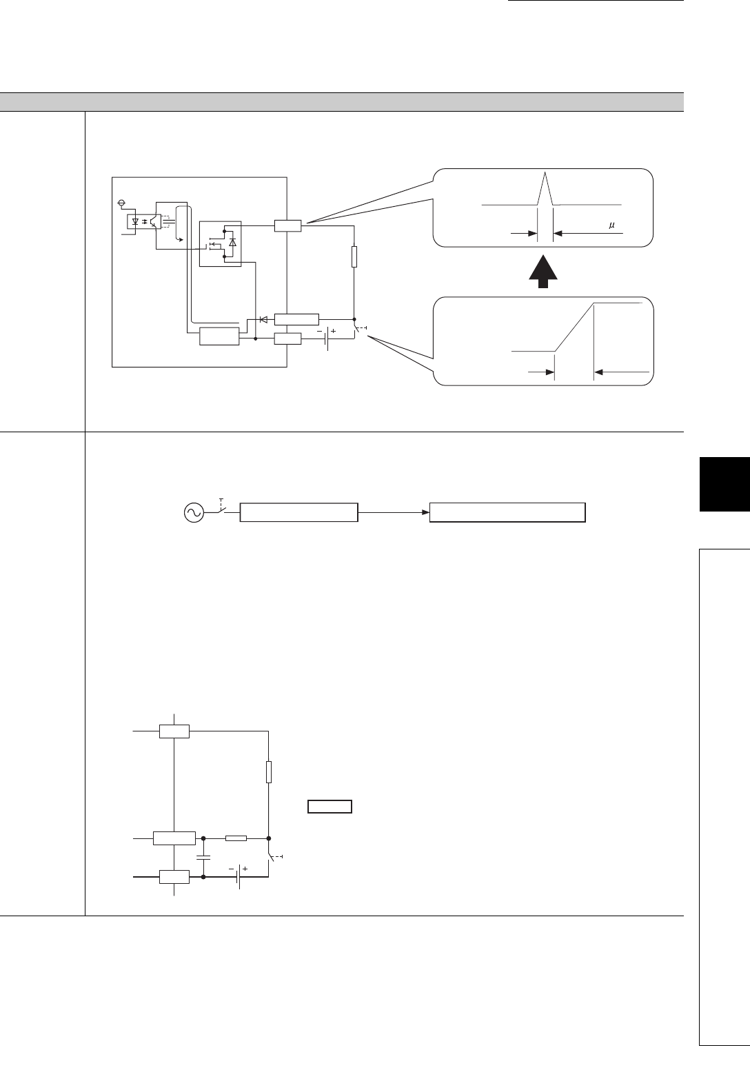
(3) A load momentarily turns on when powering on the external power supply.
Case
Cause
An incorrect output occurs due to floating capacitance(C) between collector and emitter of photocoupler.
When a high sensitivity load (such as solid state relay) is used, this incorrect output may occur.
When the rise time of voltage of the external power supply is 10ms or less, current (Ic) flows to gate of transistor (Tr1) of next stage due to
floating capacitance (C) between collector and emitter of photocoupler. Then, output Y0 turns on for approx. 100µs.
Action
Action 1: Check that the rise time of the external power supply is 10ms or more. And then, install a switch (SW1) for turning on or off
external power supply to the primary side of it.
Action 2: When installing the SW1 to the secondary side of it is required, make the rise time to 10ms or more and connect a capacitor and
resistor as shown below.
For the following source output modules, take Action 1 on the above due to no effect of Action 2 by the characteristics of the external power
supply circuit.
•LY40PT5P
•LY41PT1P
•LY42PT1P
•LH42C4PT1P
12/24VDC
Y0
C
SW
24VDC
Ic
Constant-voltage
circuit
SW: External
power supply
(24VDC) at ON
10ms or less
Output Y0
Approx.100 s
Output module
Photocoupler
COM
Tr1
Load
SW1
Secondary side
Primary side
External power supply
Programmable
controller
Output module
External power supply terminal
*1 Check the consumption current of the external power supply for modules used.
*2 Select the power capacity of resistance to be 3 to 5 times lager than the actual power
consumption.
C1: Several hundreds of microfarads 50V
Time constant
=
C1
×
R1
=
300
×
10
-6
×
40
= 12 ×
10
-3
[s]
= 12 [ms]
Power capacity ≥ (external power supply current*
1
)
2
× resistance value × (3 to 5)
*
2
Example
R1 = 40Ω, C1 = 300μF
12/24VDC
COM
Y0
24VDC
R1
C1
R1: Several tens of ohms
SW
Load
Sink type output


