


25
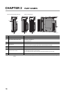
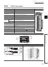
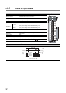
CHAPTER 3 BEFORE USING I/O MODULE
3
3.2 Output Module
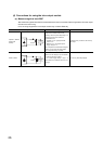
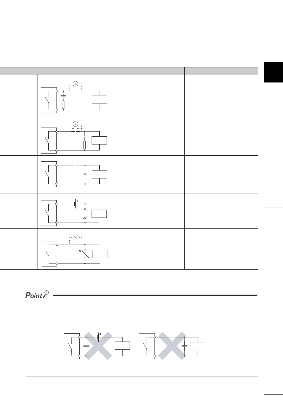
(c) Measures against back EMF
Configure a contact protection circuit for extending the contact life, preventing noise when the contact is cut off,
and suppressing the generation of carbide and nitric acid due to arc discharge.
An Incorrect contact protection circuit may cause contact welding.
Also, when using the contact protection circuit, the recovery time may be long.
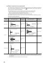
The following table shows the representative examples of the contact protection circuit.
*1 When using AC power, impedance of CR must be larger enough than it of the load (prevention of a malfunction due to
leak current from the CR).
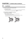
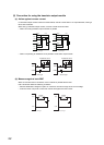
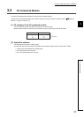
● Avoid providing a contact protection circuits shown below.
These circuit are effective for preventing an arc at shut-off. However, the contact welding may occur because the charge
current flows to capacitor when the contact turns on or off.
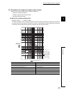
A DC inductive load is usually harder for switching than a resistor load, but if a proper protection circuit is configured, the
performance will be similar to the resistor load.
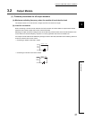
● A protection circuit must be provided closely to a load or contact (module). If their distance is far, the protection circuit
may not be effective. Appropriate distance is within 50 cm.
Example Method for selecting elements Remarks
Capacitor + Resistor
method (CR
method)
Refer to the following for constants of the
capacitor and resistor. Note that the
following values may differ depending on a
nature of the load and a variation of
characteristics of it.
• Capacitor: 0.5 to 1(µF) against load
current of 1A
• Resistor: 0.5 to 1() against power
supply voltage of 1V
Use a capacitor whose withstand voltage is
equal to or more than the rated voltage. In
AC circuit, use a capacitor having no
polarity.
If a load is a relay or solenoid, the recovery
time delays.
A capacitor suppresses electric discharge
while a contact is off, and a resistor
restricts a flow of current while a contact is
on.
Diode method
Use a diode that meets both conditions
shown below.
• Reverse breakdown voltage is equal to
or more than 10 times as large as the
circuit voltage.
• The forward current is equal to or more
than 2 times as large as the load current.
The recovery time is slower than the CR
method.
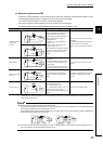
Diode + Zener diode
method
Use zener voltage for the zener diode
equal to or more than the power supply
voltage.
This method is effective when the recovery
time delays considerably by the diode
method.
Varistor method
Select a cut voltage (Vc) for the varistor to
meet the following condition.
• Vc > Power voltage × 1.5(V)
• Vc > Power supply voltage × 1.5(V) × √2
(when using AC power supply)
This method is not effective when the Vc is
too high
The recovery time delays slightly.
*1
Capacitor
Resistor
Inductive
load
Capacitor
Resistor
Inductive
load
Diode
Inductive
load
Diode
Inductive
load
Zener Diode
Varistor
Inductive
load
Capacitor
Inductive
load
Capacitor
Inductive
load