


39
CHAPTER 4 SPECIFICATIONS
4
4.3 Output Module Specifications
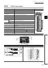
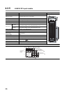
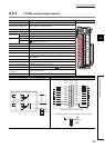
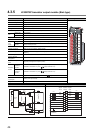
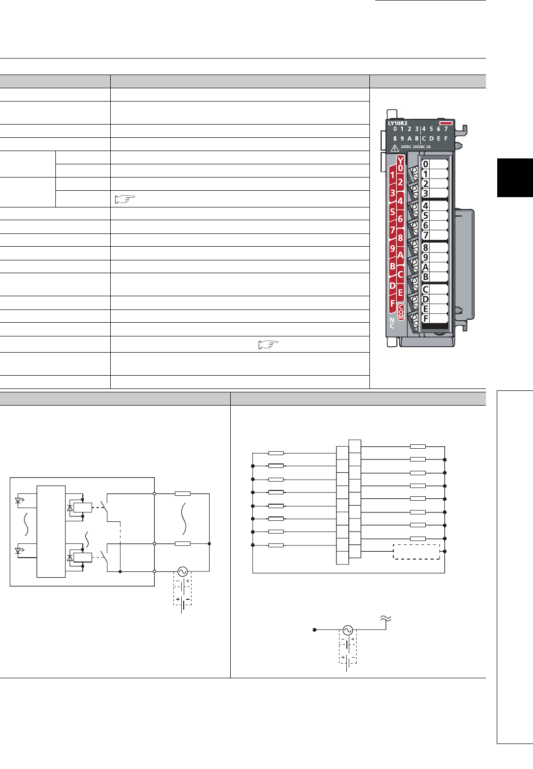
4.3.1 LY10R2 contact output module
Item Specifications Appearance
Number of output points 16 points
Rated switching voltage, current
24VDC 2A (resistance load)/point, 8A/common
240VAC 2A (COS = 1)/point, 8A/common
Minimum switching load 5VDC 1mA
Maximum switching load 264VAC 125VDC
Response time
OFF to ON 10ms or less
ON to OFF 12ms or less
Life
Mechanical 20 million times or more
Electrical
Page 23, Section 3.2 (3) (a)
Maximum switching frequency 3600 times/hour
Surge suppressor None
Fuse None
Dielectric withstand voltage 2300VAC, 1 minute (altitude 2000m)
Insulation resistance 10M or more by insulation resistance tester
Noise immunity
By noise simulator of 1500Vp-p noise voltage, 1µs noise width and 25 to 60Hz
noise frequency
Protection degree IP1X
Common terminal arrangement 16 points/common (common terminal: TB17)
Number of occupied I/O points 16 points (I/O assignment: output 16 points)
External interface
18-point screw terminal block (M3 × 6 screws) ( Page 62, Section 6.2.1)
5VDC internal current
consumption
460mA (TYP. all points ON)
Weight 0.21kg
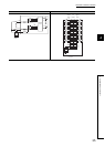
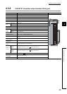
External connections Terminal connections
TB1
Load
Load
LED
TB17
TB16
LED
100/200VAC
or
24VDC
Internal
circuit
Relay
Relay
1
3
5
7
9
11
13
15
17
2
4
6
8
10
12
14
16
18
Y01
Y03
Y05
Y07
Y09
Y0B
Y0D
Y0F
Y00
Y02
Y04
Y06
Y08
Y0A
Y0C
Y0E
COM
Empty
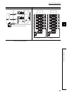
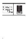
The following diagram shows the external load power supply.
100/200VAC
or
24VDC
External load
power supply
Load
Load
Load
Load
Load
Load
Load
Load
Load
Load
Load
Load
Load
Load
Load
Load
Terminal
number
Signal
name
Signal
name
Viewed from the front of the module.