


48
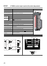
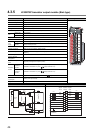
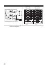
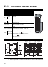
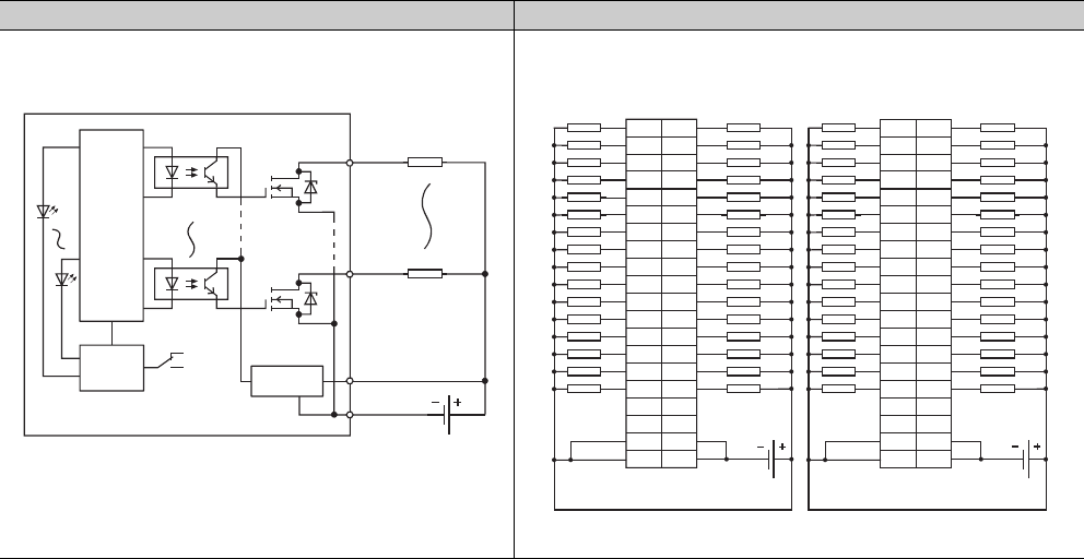
*1 Switching left side (F) provides the first half (Y00 to Y1F) LED indications, and switching right side (L) provides the latter
half (Y20 to Y3F) LED indications.
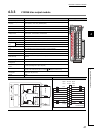
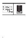
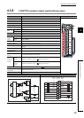
External connections Terminal connections
1B20
1A01,1A02
1B01,1B02
LED
12/24VDC
sw
1A05
Internal
circuit
Indication
selector
circuit
Constant-voltage
circuit
Photocoupler
Photocoupler
Left side connectors
(first half )
Right side connectors
(last half )
The above diagram shows the first half of 32 points (F).
The last half of 32 points (L) are similar.
*1
Load
Load
1A201B20
1A19
1B19
1B18
1B17
1B16
1B15
1B14
1B13
1B12
1B11
1B10
1B09
1B08
1B07
1B06
1B05
1B04
1B03
1B02
1A12
1A04
1A02
1B01
1A18
1A17
1A16
1A15
1A14
1A13
1A11
1A10
1A09
1A08
1A07
1A06
1A05
1A03
1A01
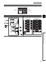
COM1
COM1
Y01
Y02
Y03
Y04
Y05
Y06
Y07
Y08
Y09
Y0A
Y0B
Y0C
Y0D
Y0E
Y0F
Y00
Y11
Y12
Y13
Y14
Y15
Y16
Y17
Y18
Y19
Y1A
Y1B
Y1C
Y1D
Y1E
Y1F
Y10
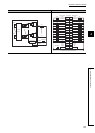
12/24VDC
12/24VDC
12/24VDC
2A202B20
2A19
2B19
2B18
2B17
2B16
2B15
2B14
2B13
2B12
2B11
2B10
2B09
2B08
2B07
2B06
2B05
2B04
2B03
2B02
2A12
2A04
2A02
2B01
2A18
2A17
2A16
2A15
2A14
2A13
2A11
2A10
2A09
2A08
2A07
2A06
2A05
2A03
2A01
COM2
COM2
Y21
Y22
Y23
Y24
Y25
Y26
Y27
Y28
Y29
Y2A
Y2B
Y2C
Y2D
Y2E
Y2F
Y20
Y31
Y32
Y33
Y34
Y35
Y36
Y37
Y38
Y39
Y3A
Y3B
Y3C
Y3D
Y3E
Y3F
Y30
12/24VDC
12/24VDC
12/24VDC
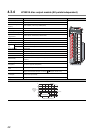
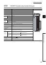
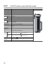
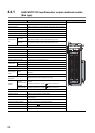
Pin
number
Signal
name
Empty
Viewed from the front of
the module.
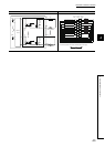
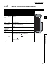
Empty
Viewed from the front of
the module.
Signal
name
Pin
number
Signal
name
Signal
name
Left side connector Right side connectors
Empty
Empty
Empty
Empty
Empty
Empty
Load
Load
Load
Load
Load
Load
Load
Load
Load
Load
Load
Load
Load
Load
Load
Load
Load
Load
Load
Load
Load
Load
Load
Load
Load
Load
Load
Load
Load
Load
Load
Load
Load
Load
Load
Load
Load
Load
Load
Load
Load
Load
Load
Load
Load
Load
Load
Load
Load
Load
Load
Load
Load
Load
Load
Load
Load
Load
Load
Load
Load
Load
Load
Load