


52 6. NetCommand
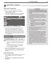
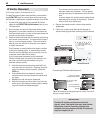
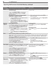
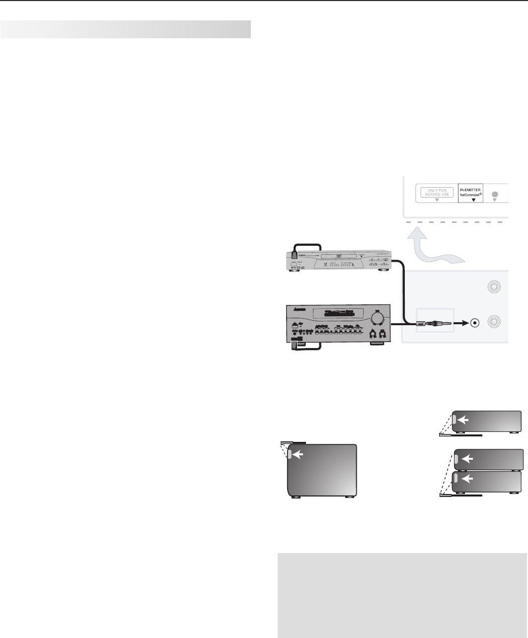
IR Emitter Placement
An IR emitter cable is included with the TV.
The NetCommand system uses emitters connected to
the
IR EMITTER
jack to control other devices such as
DVD players, cable boxes, satellite receivers, and VCRs.
1. Connect the plug end of the supplied IR emitter
cable to the
IR EMITTER NetCommand
®
jack on the
TV back panel.
2. Run the cable for each of the emitter ends under,
alongside, or over each device to be controlled so
that the emitter end is in front of the area where the
remote control sensor is located.
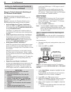
3. Position the emitter end with the emitter bulb facing
the remote control sensor. The bulb emits infrared
light in a cone-shaped pattern. Place the bulb far
enough from the sensor to allow the cone pattern
to reach the sensor.
The IR sensor is usually behind the plastic window
of the front display panel. It is sometimes visible
with the aid of a flashlight and is normally a round
or square cutout behind the plastic.
If you cannot see the sensor and the device’s
Owner’s Guide does not specify the location, you
can find it by following these steps using the
device’s remote control:
a. Hold the device’s remote about one-half inch
from the front of the device. Starting from one
end of the display window plastic, press the
POWER
key.
b. If the device does not respond, move the
remote control one inch toward the center and
try again.
c. Repeat this until the device responds.
d. Note this location and then start over from the
other end of the display window plastic, repeat-
ing until the device responds again.
The remote control sensor is somewhere
between these two positions. This is usually
enough accuracy for placement of the IR emit-
ters.
In some cases, the emitter works better facing
downward from the top of the device. Experi-
ment to find what works best.
4. Secure the emitter ends in place using double-
sided tape.
5. Place any unused ends behind the devices to
prevent stray signals from reaching the IR sensors.
#"$,*/1651"/&-
CFMPXMBCFMXJUIJOSFDFTTFE
BSFBBUUPQ
"/5."*/
57#BDL1BOFM
% *( *5"-
46 3306 /%
4
$)
"73FDFJWFS
0UIFS"7EFWJDF
Connecting IR Emitter NetCommand
*OGSPOUPGB
TJOHMFBWFSBHF
TJ[FEEFWJDF
0OUPQPGBTJOHMF
UBMMEFWJDF
*OGSPOUTIBSFE
CZUXPBWFSBHF
TJ[FEEFWJDFT
*3TFOTPS
*3TFOTPS
*3TFOTPS
*3TFOTPS
*OGSPOUPGBTJOHMF
BWFSBHFTJ[FEEFWJDF
0OUPQPGBTJOHMFUBMM
EFWJDF
*OGSPOUTIBSFECZUXP
BWFSBHFTJ[FEEFWJDFT
*3TFOTPS
*3TFOTPS
*3TFOTPS
*3TFOTPS
*3TFOTPS
*OGSPOUPGBTJOHMF
BWFSBHFTJ[FEEFWJDF
0OUPQPGBTJOHMF
UBMMEFWJDF
*OGSPOUTIBSFECZ
UXPBWFSBHFTJ[FE
EFWJDFT
*3TFOTPS
*3TFOTPS
*3TFOTPS
*3TFOTPS
*3TFOTPS
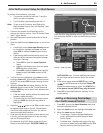
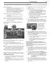
Place IR emitters so the signal can be “seen” by the IR
sensor on each device.
IMPORTANT
Position IR emitters so that each device’s
sensor “sees” the signal from only one emitter.
Otherwise, a device receiving signals from
multiple sources (remote controls, IR emitters)
may not respond at all.
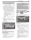
Place the emitter ends in front of each device
to be controlled and in the area where the
remote control sensor is located.