


17
17
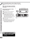
Additional connection cables are not
provided with the TV. They should be
available at most electronic stores.
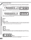
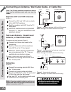
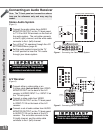
Connecting a VCR
Antennas or Wall Outlet Cable
(Figure 1)
Connect the incoming cable to ANT-A on
the TV back panel.
Connect two coaxial cables as follows:
One from LOOP-OUT on the TV back panel
to ANTENNA IN on the VCR back panel.
One from VCR back panel ANTENNA OUT
to ANT-B on the TV back panel.
Now complete Figure 3, steps 1-2.
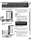
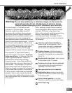
Connecting a VCR
Cable Box
(Figure 2)
Connect the incoming cable to ANT-A on
the TV back panel.
Connect three coaxial cables as follows:
One from LOOP-OUT on the TV back panel
to IN on the back of the cable box.
One from OUT on the back of the cable
box to ANTENNA IN on the VCR back
panel.
One from ANTENNA OUT on the VCR back
panel to ANT-B on the TV back panel.
Now complete Figure 3, steps 1-2.
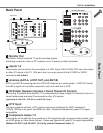
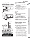
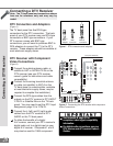
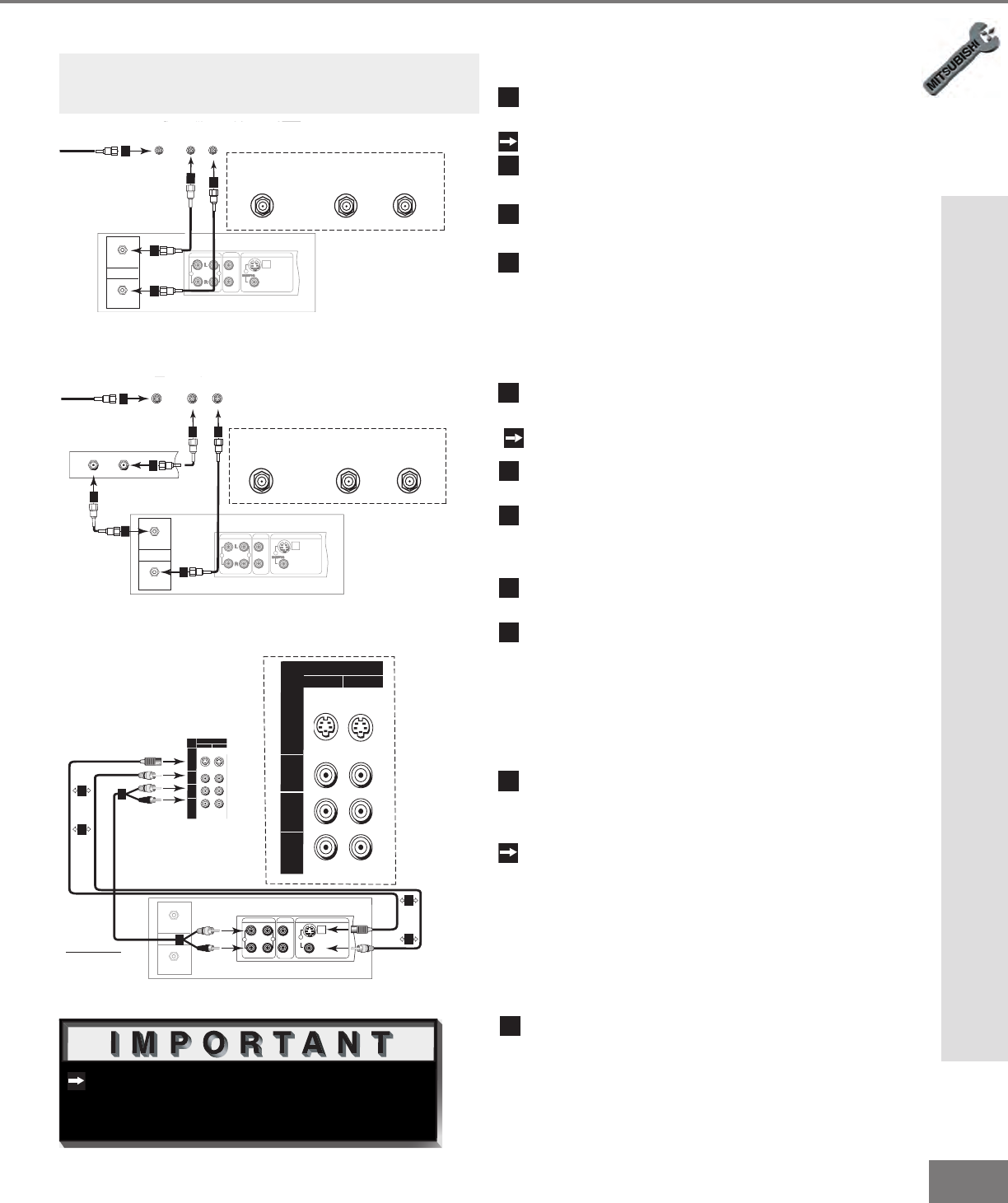
Composite Video with Audio or
S-Video with Audio
(Figure 3)
Connect a video cable from VIDEO OUT on
the VCR back panel to VIDEO INPUT-1 or
INPUT-2 on the TV back panel.
If you have an S-VHS VCR, follow the
same steps using the S-Video terminals
the VCR and TV (in place of the composite
terminals). You may connect to the
S-VIDEO or VIDEO terminal but not to
both.
Connect a set of audio cables from AUDIO
OUT on the VCR back panel to AUDIO
INPUT-1 or INPUT-2 on the TV back panel.
The red cable connects to the R (right)
channel and the white cable connects to
the L (left) channel. If your VCR is mono
(non-stereo), connect only the white (left)
cable.
COMP ONE NT
480i / 480P/ 1080i
AUDI O-
RI GHT
LE FT /
(MONO)
AUDI O-
DT V
(Y PbPr/ GBRHV)
MONITOR
I NP UT
OUT
2
1
ANT-A
ANT-B
LOOP
OUT
480i / 480P /1080i
AUDI O-
RIG HT
AUDIO-
LEF T/
(MONO)
VI DE O
S-VIDEO
2
IR EMITTER REPEATER
Y
P r
Pb
V
H
Y
G
Pb
B
P r
R
AUDIO OUT
AUDIO IN
VIDEO OUT
(Y/C)
MONITOR
1
L
R
L
R
1
2
IN
OUT
Antenna
VCR back panel
Incoming Cable
Cable Box
Rear Terminals
INOUT
1
2 4
2
3
3
4
ANT- A
ANT-B
LOOP
OUT
TV back panel (Detailed View)
CO MPON ENT
480 i / 480 P/ 1080i
AU DIO -
RI GHT
L EFT /
( MONO)
AU DIO -
DT V
(Y PbPr/ GBRHV )
MONITO R
I NP U T
OUT
2
1
ANT-A
ANT-B
LOOP
OUT
480i / 4 80P /10 80i
AUDI O-
RIG HT
AUDIO-
LEF T/
(MONO)
VI DE O
S-VIDEO
2
IR EMITTER REPEATER
Y
Pr
Pb
V
H
Y
G
Pb
B
Pr
R
AUDIO OUT
AUDIO IN
VIDEO OUT
(Y/C)
MONITOR
1
L
R
L
R
1
2
Incoming Cable
IN
OUT
Antenna
VCR back panel
1
ANT-A
ANT-B
LOOP
OUT
TV back panel (Detailed View)
2
3
2
3
2
3
4
1
1
2
3
4
5
1
2
Figure 3. Connecting the VCR Audio/Video.
Note: The TV back panel and connections shown
here are for reference only and may vary by
model.
Figure 1. Connecting VCR with antennas or wall outlet
table.
Figure 2. Connecting VCR with cable box.
CO MPON ENT
480 i / 480 P/ 1080i
AU DIO -
RI GHT
L EFT /
( MONO)
AU DIO -
DT V
(Y PbPr/ GBRHV )
MONITOR
I NP U T
OUT
2
1
ANT-A
ANT-B
LOOP
OUT
480i / 480 P /1080 i
AUDI O-
RIG HT
AUDIO-
LEF T/
(MONO)
VI DE O
S-VIDEO
2
IR EMITTER REPEATER
Y
Pr
Pb
V
H
Y
G
Pb
B
Pr
R
INPUT
2
1
AUDIO-
RIGHT
AUDIO-
LEFT/
(MONO)
VIDEO
S-VIDEO
IN
OUT
Antenna
AUDIO OUT
AUDIO IN
VIDEO OUT
(Y/C)
MONITOR
1
L
R
L
R
1
2
VCR back panel
If your VCR has a video
channel or RF ON/OFF
switch, set to OFF.
Attach
only
one
cable
type
1
1
Attach
only
one
cable
type
1
1
2
2
White
Red
White
Red
TV back panel (Detailed View)
Part ll: Installation