


18
18
COMPONENT
480i/480P/ 1080i
AUDIO -
RIGHT
LE FT /
(MONO)
AUDIO -
DT V
(YPbPr/ GBRHV)
MONITOR
I NP UT
OUT
2
1
ANT-A
ANT-B
LOOP
OUT
480i / 480P /1080i
AUD IO-
RI GHT
AUD IO-
LE FT /
(MONO)
V ID EO
S-VIDEO
2
IR EMITTER REPEATER
Y
P r
P b
V
H
Y
G
Pb
B
P r
R
Yellow
S-Video
A
b
1
1
2
3
W
h
i
t
e
White
R
e
d
Red
Yellow
MONITOR
IN PU T
OUT
2
1
AUDIO-
RI GHT
AUD IO-
LE FT /
(MONO)
V ID EO
S-VIDEO
TV back panel
(Detailed View)
AV Receiver
(M-VR900)
Back panel section
COMPONEN T
480i/ 480P/ 1080i
AUDIO -
RI GHT
LE FT /
(MONO )
AUDIO -
DT V
(Y PbPr/ GBRHV)
MONITOR
I NP UT
OUT
2
1
ANT-A
ANT-B
LOOP
OUT
480i / 480P /1080 i
AUDI O-
RI GHT
AUDI O-
LEF T/
(MONO)
VI DE O
S-VIDEO
2
IR EMITTER REPEATER
Y
P r
Pb
V
H
Y
G
Pb
B
P r
R
MONITOR
OUT
AUDIO-
RIGHT
AUDIO-
LEFT/
(MONO)
VIDEO
S-VIDEO
TV back panel (Detailed View)
Red
Red
Audio system back panel section
OUTOUT
OUT
ININININ
SUBWOOFER
(MONO)
CD
AUX TAPE
1
TAPE
2
L
R
White
White
1
Please see your A/V receiver Owner’s
Guide for more detailed connections.
Additional connection cables are not
provided with the TV. They should be
available at most electronic stores.
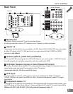
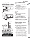
Connecting an Audio Receiver
Connecting an Audio Receiver
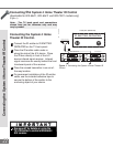
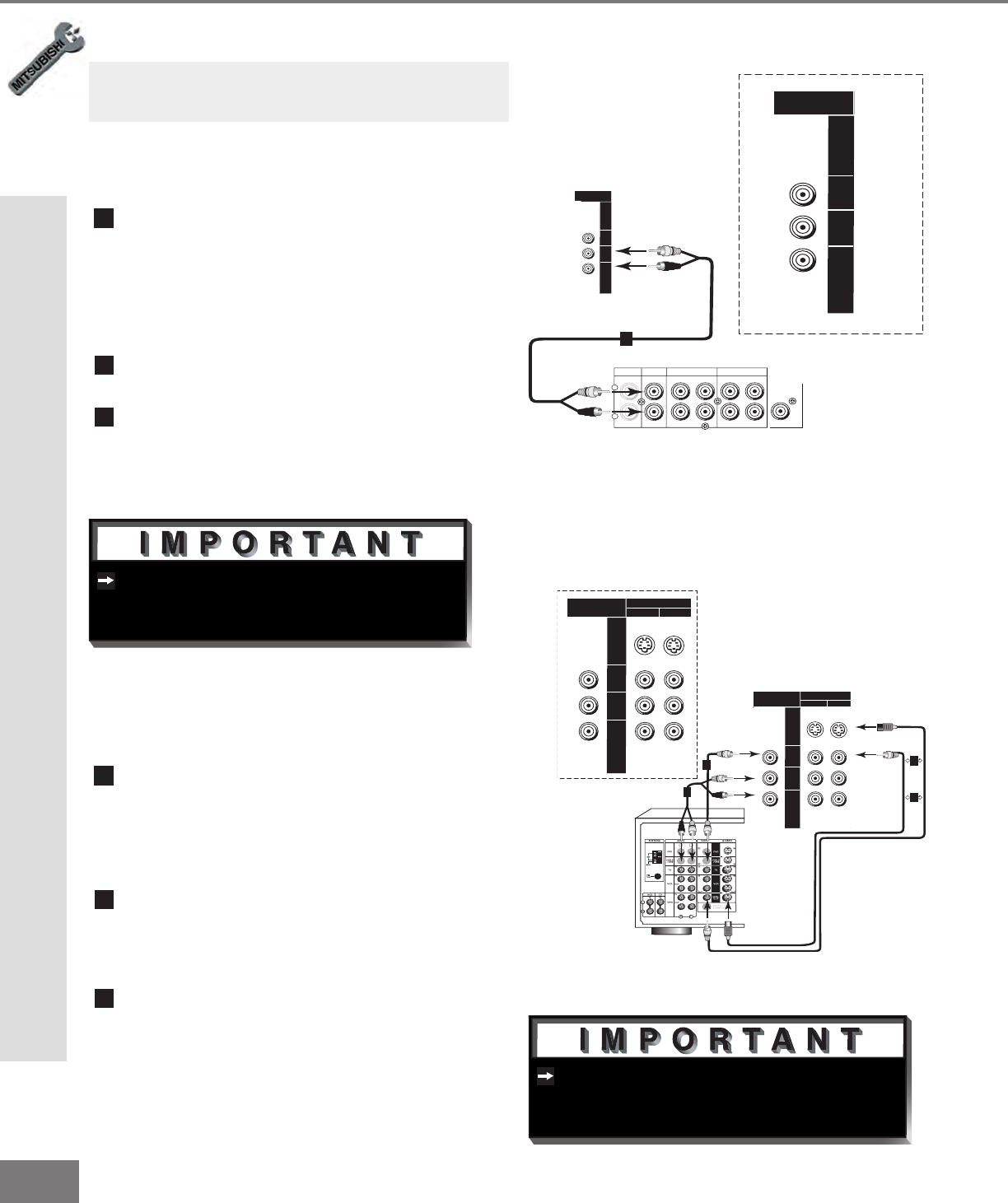
Stereo Audio System
(Figure 1)
1
Connect the audio cables from AUDIO
MONITOR OUTPUT on the TV back panel
to TV IN or AUX IN terminals on the back of
the audio system. The red cable connects
to the R (right) channel, and the white cable
connects to the L (left) channel.
2
Turn off the TV’s speakers through the A/V
SETTINGS Menu, page 48.
3
Set the audio system’s input to the TV
or AUX position to hear the TV’s audio
through your stereo system.
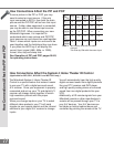
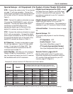
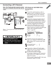
A/V Receiver
(Figure 2)
1
Connect either a video cable or an
S-Video cable (but not both) from VIDEO
MONITOR OUT on the back of the A/V
receiver to VIDEO INPUT-1 or INPUT- 2 on
the TV back panel.
2
Connect a video cable from VIDEO
MONITOR OUTPUT on the TV back panel
to VIDEO TV IN on the back of the A/V
receiver.
3
Connect a set of audio cables from AUDIO
MONITOR OUTPUT on the TV back panel
to AUDIO TV IN on the back of the A/V
receiver. The red cable connects to the
R (right) channel, and the white cable
connects to the L (left) channel.
Figure 1. Connecting the Stereo Audio System.
Figure 2. Connecting the A/V Receiver.
Note: The TV back panel and connections shown
here are for reference only and may vary by
model.