


12
Chapter . . .
ANT-A
ANT-B
LOOP
OUT
WS-48413, WS-55413, WS-65413
Back Panel
COMPONENT
480i/480P/1080i
2
1
Y
Pr
Pb
AUDIO-
RIGHT
LEFT/
(
M
O
N
O
)
AUDIO-
Y
G
Pb
B
Pr
R
V
H
DTV(YPbPr/GBRHV)
480i/480P/1080i
INPUT
2
1
AUDIO-
RIGHT
AUDIO-
LEFT/
(MONO)
VIDEO
S-VIDEO
M
O
N
I
T
O
R
OUT
SERVICEWARNING
MONITORLINK
TM
/DVI
AUDIO-
LEFT/
(MONO)
AUDIO-
RIGHT
CAUTION:
TOMEASURESECONDANODEVOLTAGEUSEAHIGHVOLTAGEMETER
CONNECTEDFROMANODELEADTOCHASSISONLY.DISCHARGEHIGHVOLTAGETOCHASSIS
ONLY,NOTTOEXTERNALGROUND.
WARNING:
HANDLEWITHCAREHIGHVACUUMPICTURETUBEISDANGEROUSTO
HANDLE.REFERSERVICINGTOQUALIFIEDSERVICEPERSONNEL.REPLACEWITHATUBE
OFTHESAMETYPENUMBERFORCONTINUEDSAFETY.
X-RAYPRECAUTION:
THISPRODUCTINCLUDESCRITICALMECHANICALAND
ELECTRICALPARTSWHICHAREESSENTIALFORX-RADIATIONSAFETY.FORCONTINUED
SAFETYREPLACECRITICALCOMPONENTSINDICATEDINTHESERVICEMANUALONLYWITH
EXACTREPLACEMENTPARTSGIVENINTHEPARTSLIST.REFERTOSERVICEMANUALFOR
OPERATINGHIGHVOLTAGEATMINIMUMBRIGHTNESS,MEASUREMENTPROCEDURESAND
PROPERSERVICEADJUSTMENTS.
1
2
3
4
5
6
7
8
MONITORLINK
TM
CONTROL
RS-232C
IREMITTER
R
NetCommand IR
REPEATER
9
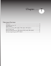
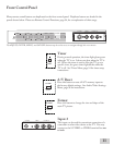
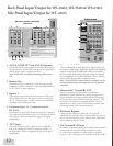
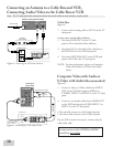
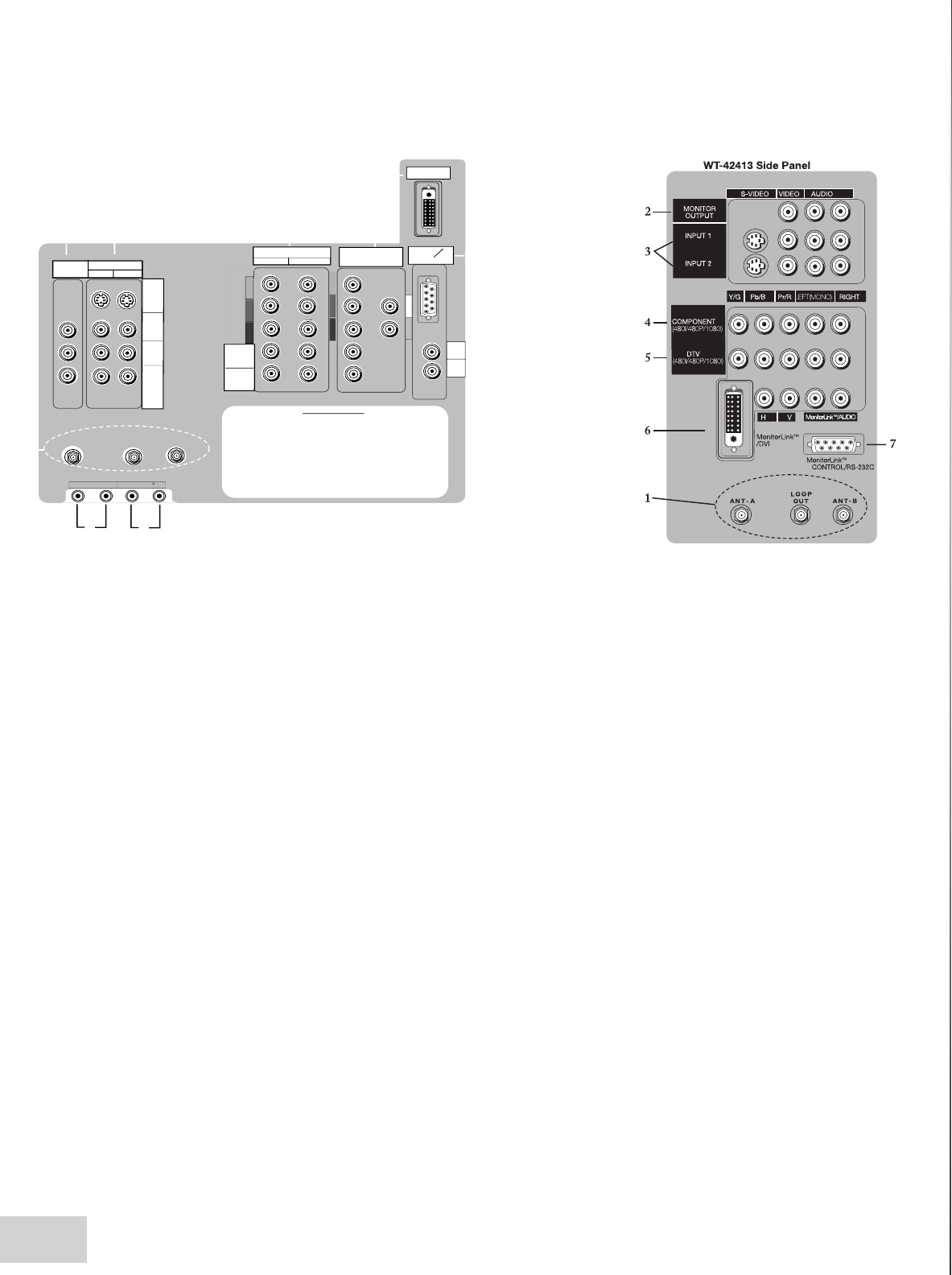
1. ANT-A, LOOP OUT and ANT-B (Antenna)
ANT-A and ANT-B receive signals from VHF/UHF antennas
or a cable system. LOOP OUT sends the ANT-A signal out to
another device, such as a cable box or VCR.
Note: LOOP OUT is disabled when Energy Mode is set to
Low.
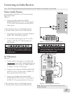
2. Monitor Out
The Monitor Output sends the TV audio and video signals
(excluding component video, DTV video and MonitorLink) to
an A/V receiver or other equipment.
3. Inputs 1-2
These inputs can be used for the connection of a VCR, Super
VHS (S-VHS) VCR, laser disc player, or other A/V device to
the TV. With each input, you may connect to the S-VIDEO
or VIDEO terminal but not to both.
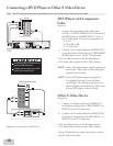
4. Component Inputs 1-2 (Component only for
WT-42413)
These inputs can be used for the connection of A/V equipment
with component video outputs, such as a DVD player or Video
Game System. Please see Appendix B, page 67, for signal
compatibility.
5. DTV Input
This input is used to connect a DTV receiver or cable box
and can be configured for HDTV component (YPbPr), or
RGB plus H&V. Please see Appendix B, page 67, for signal
compatibility.
Back Panel Input/Output for WS-, WS- & WS-
Side Panel Input/Output for WT-
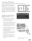
6. MonitorLink™/DVI
This is a Mitsubishi-exclusive proprietary digital interface for
the display of high quality digital video signals from Mitsubishi
products such as the HD-5000 HDTV Receiver/Controller.
All video signals, both analog and digital can be sent digitally
to your Mitsubushi TV from the HD-5000. This can also be
used as a DVI input for other compatible sources.
Note: The DVI-HDTV input terminal is compliant with the
EIA-861 standard and is not intended for use with personal
computers.
7. MonitorLink™ Control/RS-232C
A digital control interface that works in parallel with
MonitorLink. While MonitorLink provides the digital video
signal, MonitorLink Control provides enhanced functioning
such as automatic power ON/OFF and input selection. This
can also be used with other compatible RS-232C external
control devices. Please visit www.mitsubishi-tv.com for more
information on RS-232C command structure.-
8. IR Emitter Repeater
Connecting IR emitters here allows the TV to pass IR
commands from most IR remote controls to other A/V devices
that are out of range of the remote control. Note: This feature
is not available on the WT-42413.
. Net Command® IR Input
IR emitters connected to these jacks are used by NetCommand
system of the TV to control external analog devices such
as VCRs, DVDs, cable boxes, satellite receivers and audio
receivers. Note: This feature is not available on the WT-42413.