


16
17
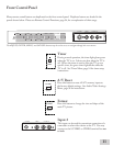
TVbackpanel(sectiondetail)
INPUT
2
1
AUDIO-
RIGHT
AUDIO-
LEFT/
(MONO)
VIDEO
S-VIDEO
M
O
N
I
T
O
R
OUT
Yellow
S-Video
Attach
only
one
cable
type
Yellow
White
Red
Red
White
Yellow
AV Receiver (back panel section)
2
3
1
1
2
3
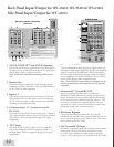
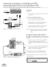
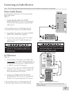
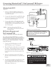
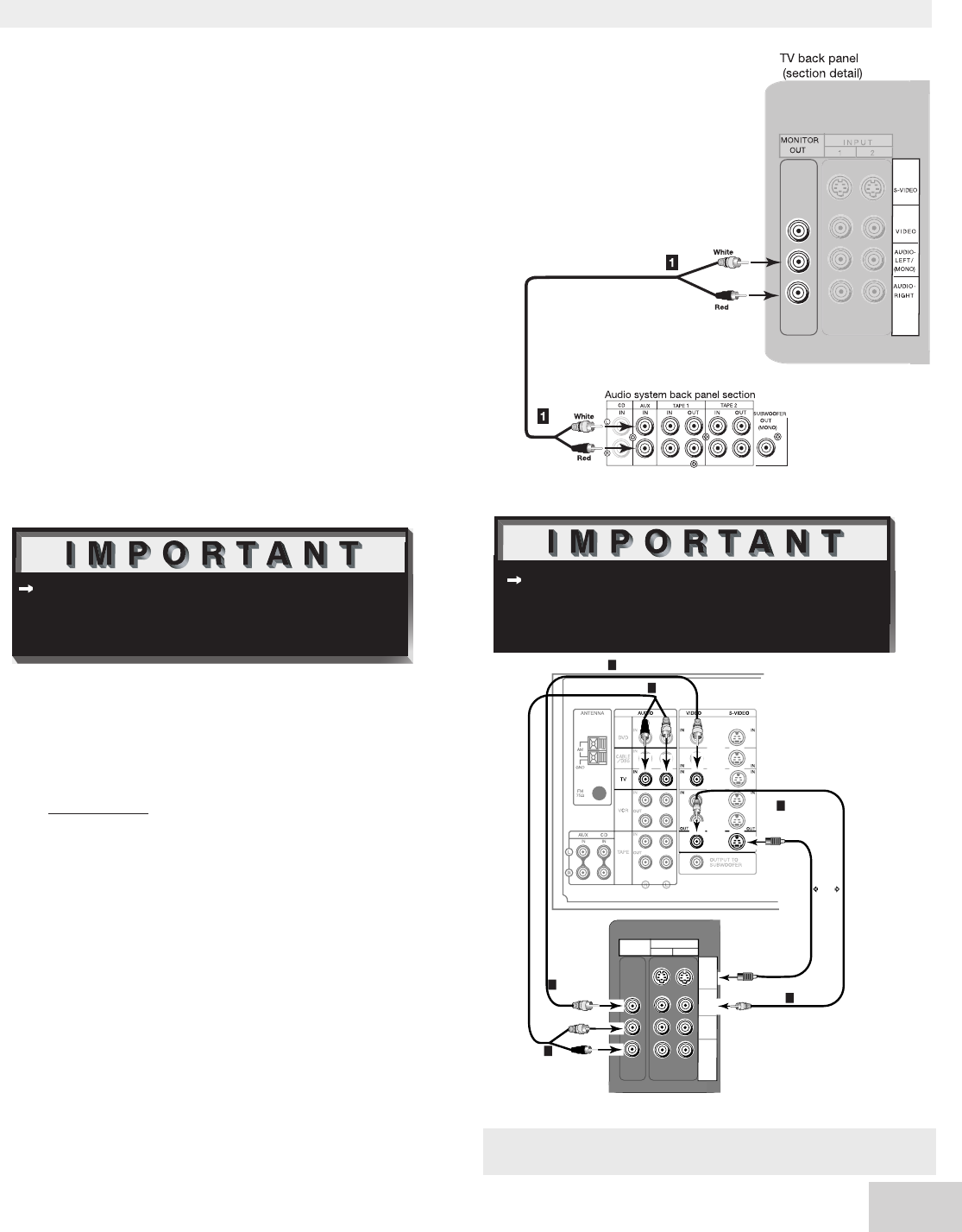
Connecting an Audio Receiver
Stereo Audio System
(recommended for shelf units or A/V receivers without
digital audio inputs)
(Figure 7)
1.
Connect the audio cables from AUDIO
MONITOR OUTPUT on the TV back panel to
TV IN or AUX IN terminals on the back of the
audio system.
• The red cable connects to the R (right) channel
• The white cable connects to the L (left) channel
2. Turn off the TV’s speakers through the AUDIO/
VIDEO SETTINGS Menu, page 58.
3. Set the audio system’s input to the TV or AUX
position to hear the TV’s audio through your
stereo system.
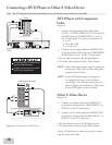
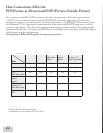
A/V Receiver
(Figure 8)
1.
Connect either a video cable or an S-Video cable
(but not both) from VIDEO MONITOR OUT on
the back of the A/V receiver to VIDEO INPUT-1
or INPUT- 2 on the TV back panel.
2.
Connect a video cable from VIDEO MONITOR
OUTPUT on the TV back panel to VIDEO TV
IN on the back of the A/V receiver.
3. Connect a set of audio cables from AUDIO
MONITOR OUTPUT on the TV back panel to
AUDIO TV IN on the back of the A/V receiver.
• The red cable connects to the R (right) channel
• The white cable connects to the L (left) channel
Note: The TV back panel and connections shown here are for reference only and may vary by model.
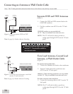
Additional connection cables are not provided
with the TV. They should be available at most
electronic stores.
Figure 7. Connecting the Stereo Audio System.
Figure 8. Connecting the A/V Receiver.
Note: Please see your A/V receiver Owner’s Guide for more
detailed connections.
These types of audio connection do NOT support
multi-channel digital audio. Please refer to your
device’s Owner’s Guide to verify.