


16
17
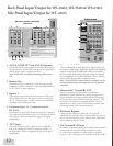
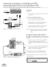
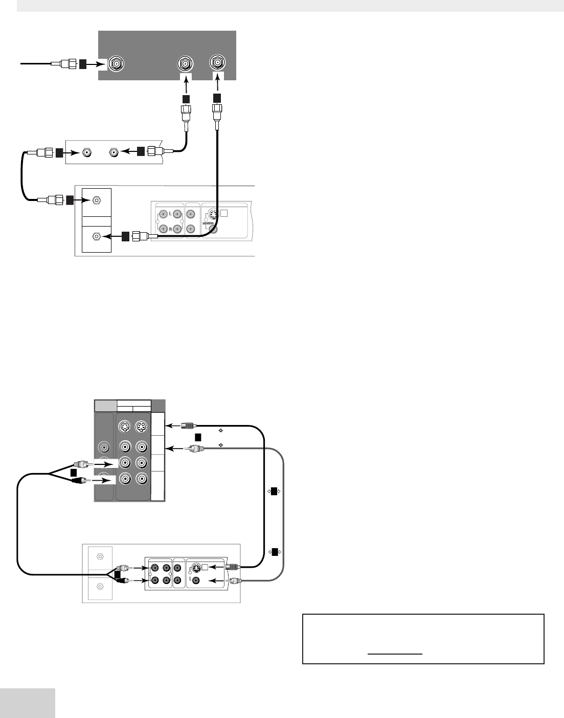
Connecting an Antenna to a Cable Box and VCR,
Connecting Audio/Video to the Cable Box or VCR
IN
OUT
Antenna
AUDIOOUT
AUDIOIN
VIDEOOUT
(Y/C)
MONITOR
1
L
R
L
R
1
2
VCR back panel
If your VCRhas avideo
channel or RFON/OFF
switch, set toOFF.
Attach
only
one
cable
type
1
1
Attach only
one cable type
1
2
2
White
Red
White
Red
TV back panel
(section detail)
INPUT
2
1
AUDIO-
RIGHT
AUDIO-
LEFT/
(MONO)
VIDEO
S-VIDEO
M
O
N
I
T
O
R
OUT
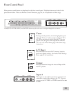
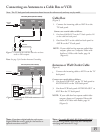
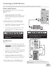
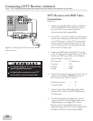
Figure 6. Connecting the VCR Audio/Video.
Note: The TV back panel and connections shown here are for reference only and may vary by model.
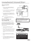
Cable Box
(Figure 5)
1.
Connect the incoming cable to ANT-A on the TV
back panel.
Connect three coaxial cables as follows:
2. One from LOOP-OUT on the TV back
panel to IN on the back of the cable box.
3. One from OUT on the back of the cable box to
ANTENNA IN on the VCR back panel.
4. One from ANTENNA OUT on the VCR back
panel to ANT-B on the TV back panel.
NOTE: For best performance, please see Composite
Video with Audio or S-Video with Audio,
below.
Composite Video with Audio or
S-Video with Audio (Recommended)
(Figure 6)
1.
Connect a video or S-Video cable from VIDEO
OUT on the VCR back panel to VIDEO or
S-VIDEO, INPUT-1 or INPUT-2 on the TV back
panel.
2. Connect a set of audio cables from AUDIO OUT
on the VCR back panel to AUDIO INPUT-1 or
INPUT-2 on the TV back panel.
• The red cable connects to the R (right) channel
• The white cable connects to the L (left) channel
If your VCR is mono (non-stereo), connect only the
white (left) cable.
AUDIO OUT
AUDIO IN
VIDEO OUT
(Y/C)
M
O
N
I
T
O
R
1
L
R
L
R
1
2
IN
OUT
Antenna
VCR back panel
Incoming Cable
Cable Box
Rear Terminals
IN
OUT
2
3
4
TV back panel (section detail)
ANT- A
1
4
ANT-B
2
LOOP
OUT
3
Figure 5. Connecting the VCR with cable box.
You may connect to the S-VIDEO or VIDEO
terminal but not to both.