16
17
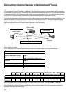
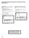
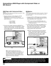
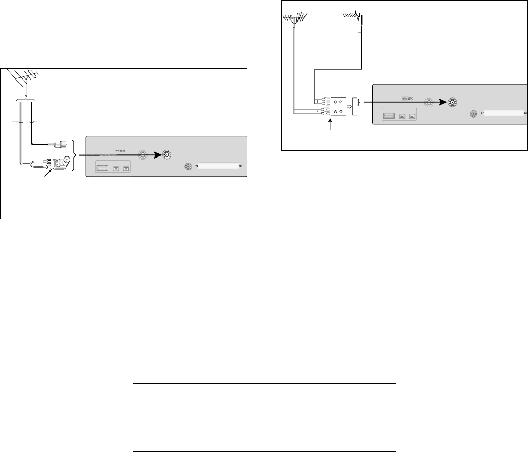
Separate UHF and VHF Antennas
Figure 4
A UHF/VHF combiner is required. This is not included with
the TV.
1. Connect the UHF and VHF antenna leads to the
UHF/VHF combiner.
2. Push the combiner onto ANT-1 MAIN on the TV
back panel.
External
Antenna
orCable
Back
Side
FlatTwinLead
UHFAntenna
(Channels14-69)
VHFAntenna
(Channels2-13)
300Ohmto
75Ohm
Combiner
FlatTwinLead
UHF
VHF
TVbackpanel(sectiondetail)
SERVICE
PORT
IEEE1394
INPUT/OUTPUT
DIGITAL
AUDIO
CableCARDSLOT
ANT-2
AUX
ANT-1
MAIN
–(DTV/CABLE/VHF/UHF)–
1.
2.
Figure 4. Connecting separate UHF and VHF Antennas
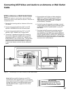
Connecting a Single Analog Antenna or Separate UHF and
VHF Antennas
Single Antenna (not for use with CableCARD™)
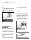
Figure 3
A 300-Ohm to 75-Ohm transformer is required. This is not
included with the TV.
For antennas with twin flat lead
1. For antenna with twin flat leads, connect the
300-Ohm twin leads to the 300-Ohm to 75-Ohm
transformer.
2. Push the 75-Ohm side of the transformer onto ANT-1
MAIN on the TV back panel.
For antennas with coaxial lead
3. Connect the coaxial lead directly to ANT-1 MAIN on
the TV back panel.
SERVICE
PORT
IEEE1394
INPUT/OUTPUT
DIGITAL
AUDIO
CableCARD
TM
SLOT
ANT-2
AUX
ANT-1
MAIN
–(DTV/CABLE/VHF/UHF)–
300-Ohm
FlatTwin
Lead
Optional300-Ohm
to75-Ohm
MatchingTransformer
75-Ohm
Coaxial
Cable
TVbackpanel(sectiondetail)
3.
2.
1.
Figure 3. Connecting an Antenna
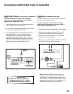
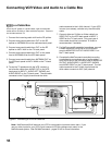
Mitsubishi strongly recommends against using
antennas with twin flat leads. Twin flat lead
antenna wires are subject to interference which
may adversely affect the performance of the TV.
We recommend using coaxial antenna cable.


