


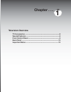

15
Additional connection cables are
not provided with the TV. They are
available at most electronic stores.
IMPORTANT
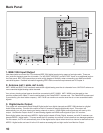
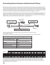
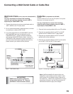
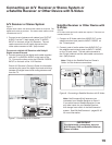
Connecting a Wall Outlet Cable or Cable Box
Wall Outlet Cable (can be used with a CableCARD™)
Figure 1
It is very important to connect the incoming
cable for your primary viewing source to ANT-1,
especially for CableCARD™ use.
1. Connect the primary incoming coaxial lead cable to
ANT-1 MAIN on the TV back panel.
2. For an optional secondary antenna source, connect
an antenna (or cable) to ANT-2 AUX.
3. If you have subscribed to a CableCARD™ service,
the CableCARD can now be inserted into the
CableCARD SLOT. Using a phillips screwdriver,
remove the CableCARD cover screws. Insert the
CableCARD, then replace the cover and screws. If
you need more information regarding this service,
please contact your cable service provider.
DIGITAL
E1394
T/OUTPUT
AUDIO
ANT-2
AUX
ANT-1
MAIN
CableCARD
TM
SLOT
– (DTV/CABLE /VHF/UHF) –
E
1
3
9
4
T
/
T
T
O
U
T
P
U
T
1.
2.
TV back panel
(section detail)
Optional
Secondary
Antenna
or Cable
Primary
Wall Outlet
Cable
3. CableCARD
TM
SLOT
(cover removed)
D
I
G
I
T
A
T
T
L
A
U
D
I
O
Figure 1. Wall Outlet Cable
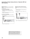
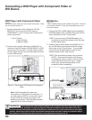
Cable Box (compatible with PIP/POP)
Figure 2
3 coaxial cables and one two-way RF splitter are required.
These are not included with the TV.
It is very important to connect the incoming
cable for your primary viewing source to ANT-1,
especially for CableCARD™ use.
1. Connect the incoming cable to IN on an RF splitter.
2. Connect one coaxial cable from OUT on the RF
splitter to ANT-1 MAIN on the TV back panel.
3. Connect one coaxial cable from OUT on the RF
splitter to IN on the cable box.
4. Connect one coaxial cable from OUT on the cable
box to ANT-2 AUX on the TV back panel.
Note: NetCommand® will assume that your
Cable Box is connected as shown above. Also,
that Channel 3 is the default output channel for
the cable box. If either the connections or output
channel are different, use the Change option of
Edit NetCommand to apply the changes.
Figure 2. Connecting a Cable Box
Cable Box
back panel section
IN
DIGITAL
UT
AUDIO
ANT-2
AUX
ANT-1
MAIN
CableCARD SLOT
– (DTV/CABLE /VHF/UHF) –
Incoming
Cable
U
T
OUT
D
I
G
I
T
A
TT
L
A
U
D
I
O
C
a
b
l
e
C
A
R
D
S
L
O
T
IN
OUT
OUT
TWO WAY SPLITTER
1.
2.
2.
3.
3.
4.
4.
TV back panel (section detail)