20
Connecting a DVD Player with Component Video or
DVI Device
DVD Player with Component Video
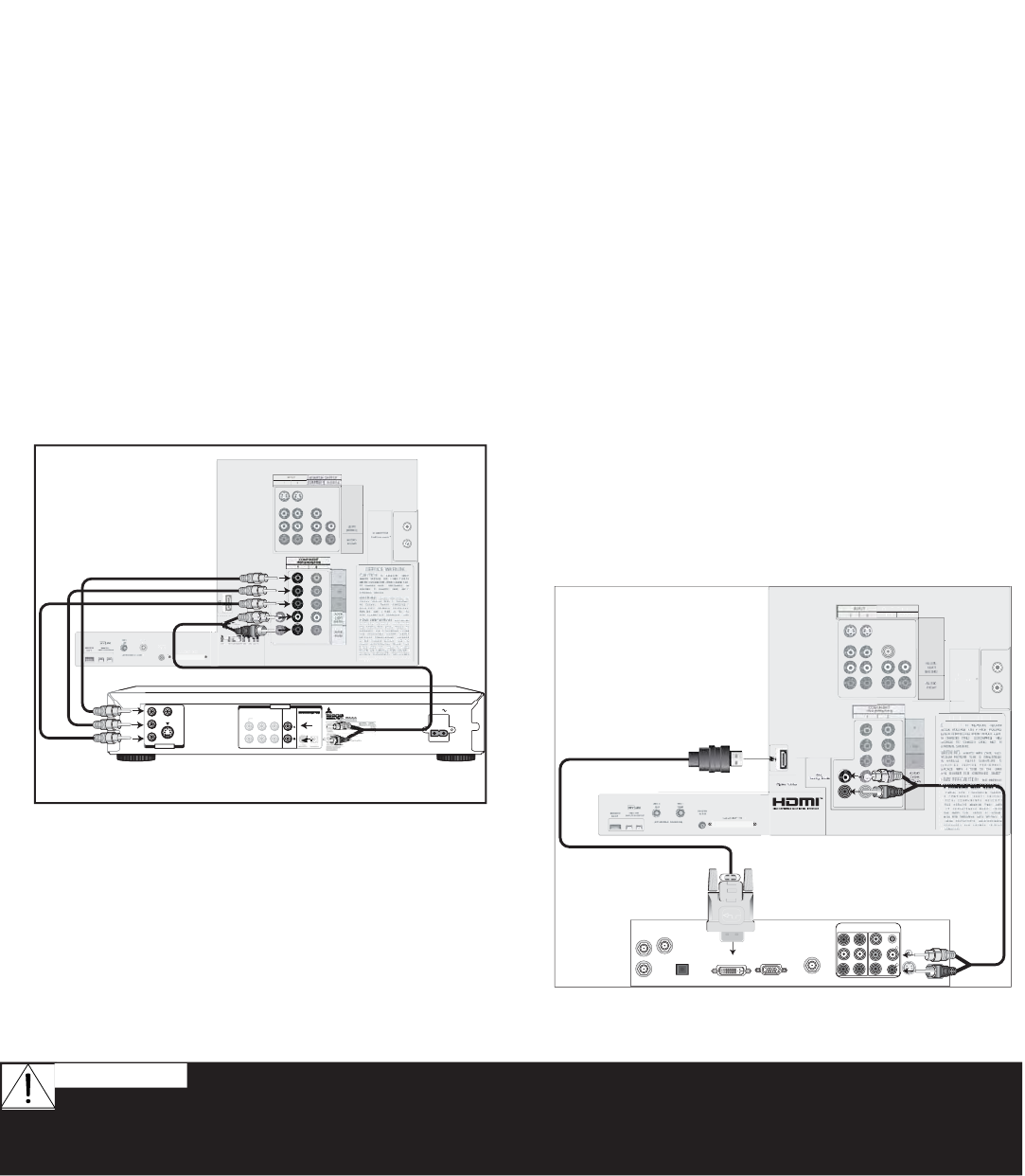
Figure 9
Component video cables and audio cables are required. These
are not included with the TV.
1. Connect component video cables from Y/Pr/Pb
VIDEO OUT on the back of the DVD player to
COMPONENT-1 on the TV back panel, matching the
correct connection:
• Y to Y (Green)
• Pr to Pr (Red)
• Pb to Pb (Blue)
2. Connect a set of audio cables from AUDIO OUT on
the back of the DVD player to COMPONENT-1 AUDIO
Input on the TV back panel. The red cable connects
to the R (right) channel, and the white cable connects
to the L (left) channel.
R
E
E
N
P
ER V
H
I
D
M
l
RD
TV back panel
V
IDEO
S
Y
C
B
CR
VIDEO OUT
BITSTREAM/PCM5.1 CH SURROUND 2CH
L
R
CENTER
SUBWOOFERSURROUND FRONT
AUDIO OUT
AC IN
MITSUBISHI
R
D-5000
DVD back panel
White
Red
White
Red
1.
1.
2.
2.
COMPONENT
YPbPr (480i/480p/1080i)
21
Note: NetCommand® will assume you
connected your DVD player to Component-1. If
you add a second DVD or use any other inputs
for your DVD, this change must match in the
NetCommand system. See Edit NetCommand...
pages 35-42 for more information.
Figure 9. Connecting a DVD Player with Component
Video
Do not display the same stationary images on the screen for more than 15% of your total TV
viewing in one week. Examples of stationary images are letterbox top/bottom bars from DVD or other video
sources, side bars when showing standard TV pictures on widescreen TV’s, stock market reports, video game
patterns, station logos, black or bright closed caption backgrounds, web sites or stationary computer images.
Such patterns can unevenly age the picture tubes causing permanent damage to the TV.
WARNING:
DVI Device
Figure 10
A DVI-to-HDMI cable and audio cables are required. These are
not included with the TV. They may be available at your local
electronics retailer.
1. Connect the DVI-to-HDMI cable (recommended) (or
DVI/HDMI adaptor with an HDMI cable) from the DVI
device back panel to the TV back panel.
NOTE: If you are using a DVI/HDMI adaptor, it is
important to connect the adaptor to the DVI side
for best performance.
2. Connect a set of audio cables from AUDIO OUT on
the the DVI device back panel to the DVI Analog
Audio input on the TV back panel. The red cable
connects to the R (right) channel, and the white
cable connects to the L (left) channel.
NOTE: This connection supports copy protection
(HDCP). Some devices require connecting to
an analog input first, in order to view on-screen
menus and select DVI as the ouput. Please
review your equipment instructions for DVI
connectivity and compatibility.
A
N
TV back panel
DigitalVideo
DigitalAudio
ANT
CABLE
SATELLITE
TV OUT
AUDIO
R
L
DVIOUT
DVI DEVICE
RGBOUT
HDMI TO DVI CABLE
AUDIO-
LEFT/
(MONO)
AUDIO-
RIGHT
DVI
AnalogAudio
1.
2.
2.
1.
Figure 10. Connecting a DVI Device


