


19
For digital audio connections, see your
A/V Receiver, DVD and Satellite Receiver
Owner’s Guides.
IMPORTANT
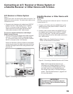
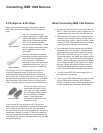
A/V Receiver or Stereo System
Figure 7
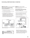
A digital audio cable and stereo audio cables are required. The
digital audio cable is provided. The stereo audio cables are not
included with the TV.
1. Connect a set of stereo audio cables from OUTPUT
AUDIO 2 on the TV back panel to the TV AUDIO
INPUT on the back of the A/V Receiver. The red
cable connects to the R (right) channel and the
white cable connects to the L (left) channel.
To connect a digital A/V Receiver with Dolby®
Digital surround sound:
2. Connect one end of the digital audio cable supplied
with the TV to DIGITAL AUDIO on the back of the
TV. Connect the other end to the COAXIAL DIGITAL
INPUT on the back of the A/V Receiver.
Check A/V Receiver’s Owner’s Guide for information
concerning the use of the digital input and switching
between the digital sound and analog stereo sound
from the TV.
A
D
J
U
S
T
M
E
N
T
S
.
I
R
E
M
I
T
T
E
R
N
e
t
C
o
m
m
a
n
d
R
D
I
G
I
T
A
T
T
L
A
U
D
I
O
A
N
T
-
T
T
1
M
A
I
N
C
a
b
l
e
C
A
R
D
T
L
E
/
V
/
/
H
F
/
U
H
F
)
–
I
N
P
U
T
1
2
C
O
M
Y
P
b
P
r
(
4
1
IN IN IN IN IN IN IN INOUT OUT OUT OUT
AUX CD TAPE1 TAPE 2 VCR 1 VCR 2 TV DVD
MONITOR VCR1 VCR 2 TV DVD
MONITOR VCR1 VCR 2 TV DVD
OUT
OUT
IN
IN
IN
IN
IN
IN
IN
IN
OUT OUT
OUT OUT
CENTER
SUB
WOOFER
FRONTSUR.
REC
SOURCE
LINE OUT
PRE OUT
SURROUND
SPEAKERS (6Ω MIN. )
FRONT
SPEAKERS-A (6Ω MIN.)
FRONT
SPEAKERS-B (6Ω MIN. )
CENTER
(6Ω MIN.)
L
L
L
L
L
R
R
R
R
THIS DEVICE COMPLIES WITH PART15 OF THE
FCC RULES.OPERATIONIS SUBJECT TO THE
FOLLOWING TWO CONDITIONS: (1) THIS DEVICE
MAYNOT CAUSE HARMFUL INTERFERENCE AND
(2) THIS DEVICE MUST ACCEPT ANY INTERFERENCE
RECEIVED, INCLUDING INTERFERENCE THATMAY
CAUSE UNDESIRED OPERATION.
MANUFACTUREDUNDER LICENSE FROM DOLBY LABORATORIES LICENSING
CORPORATION. "DOLBY", "PRO LOGIC" AND THE DOUBLE-D SYMBOL ARE
TRADEMARKSOF DOLBY LABORATORIES CORPORATION.
COPYRIGHT1992 DOLBY LABORATORIES, INC. ALL RIGHTS
RESERVED
INPUT-1
(OPTICAL)
INPUT-2
(COAXIAL)
INPUT-3
(COAXIAL)
DIGITAL AUDIO
SWITCHED
UNSWITCHED
AC120V - 60Hz
TOTAL100W, 0.9A MAX
AC OUTLETS
MITSUBISHI
AUDIO/VIDEORECEIVER
MODELM-VR1000
POWERSUPPLY
POWERCONSUMPTION
120V-60Hz
552W,732VA
DISTRIBUTEDBY
MITSUBISHICONSUMER ELECTRONICS AMERICA
INC.
6100ATLANTIC BLVD MADEIN
JAPAN
NORCROSS,GA30071-1305FABRIQUE EN
JAPAN
!
AVIS
RISQUEDE CHOC ELECTRONQUE
NEPAS ENLEVER
RISKOF ELECTRIC SHOCK
DONOT OPEN
ANTENNA
75Ω
300Ω
FM
AM
GND
ATUO
STANDBY
ON
OFF
σ
τ
S-VIDEO
VIDEO
AUDIO
WARNING
A/V Receiver Rear Panel
Useonlyif
connecting
a Dolby Digital
A/V Receiver
DIGITAL
AUDIO
AUDIO-
LEFT/
(MONO)
AUDIO-
RIGHT
MONITOR OUTPUT
AUDIO 2
2.
2.
1.
Red
White
Red
White
1.
TV back panel
AUDIO/VIDEO1
Figure 7. Connecting an A/V Receiver
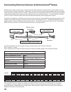
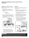
Connecting an A/V Receiver or Stereo System or
a Satellite Receiver or Other Device with S-Video
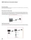
Satellite Receiver or Other Device with
S-Video
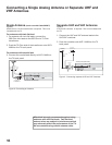
Figure 8
An S-Video cable and audio cables are required. These are not
included with the TV.
1. Connect an S-Video cable from VIDEO OUT on the
satellite receiver back panel to INPUT-2 VIDEO on
the TV back panel.
2. Connect a set of audio cables from AUDIO OUT on
the satellite receiver back panel to INPUT-2 AUDIO,
on the TV back panel. The red cable connects to
the R (right) channel and the white cable connects to
the L (left) channel.
Note: Refer to the Satellite Receiver Owner’s
Guide for Dish Antenna connections.
M
I
N
I
M
U
M
B
R
I
G
H
T
N
E
S
S
,
M
E
A
S
U
R
E
M
E
N
T
P
R
O
C
E
D
U
R
E
S
A
N
D
P
R
O
P
E
R
S
E
R
V
I
C
E
A
D
J
U
S
T
M
E
N
T
S
.
D
I
G
I
T
A
T
T
L
A
U
D
I
O
C
a
b
l
e
C
A
R
D
T
M
S
L
O
T
1
D
I
O
-
TV back panel
(Y/C)
L
R
L
R
1
2
VIDEO OUT
AUDIO OUT
AUDIO IN
Any S-Video Device
White
Red
R
2
1.
White
Red
1.
2.
2.
INPUT
12
Note: NetCommand® will asssume you
connected your Satellite Receiver to Input-2.
If you add a second Satellite Receiver or use
any other inputs for your Satellite Receiver,
this change must match in the NetCommand
system. See Edit NetCommand... pages 35-42
for more information.
Figure 8. Connecting a Satellite Receiver with S-Video